

Over the years, I’ve tried a number of methods to create an inexpensive color sensor. One way is to surround an ordinary photocell with a red, green, and blue ultra-bright LED.

Color sensor fully powered.
All three LEDs are never actually turned on at the same time. Each LED is turned on one at a time and the intensity of light reflected back to the cadmium-sulfide photocell is measured. An analog-to-digital converter measures the voltage divided between a fixed resistor (usually between 470 ohms and 10,000 ohms) and the photosensitive resistor (the photocell).
Ultra-bright LEDs are available from any electronics seller or eBay. Back when I first wrote this article, I got the LEDs from AllElectronics. I purchased red #LED-50 for $0.50, true green #LED-57 for $3.75, and blue #LED-58 for $3.50. Prices have come down considerably since then.
The advertised brightness of red is 3000 mcd, green is 3000 mcd, and blue is 1200 mcd. The resistor values that provided equivalent readings reflecting off white paper are red with 100 ohms, green with 800 ohms, and blue with 100 ohms. Either the green LED is a lot brighter than the others or the photocell’s peak sensitivity is to green (or probably some combination of both).

Color sensor turned off, showing electrical tape.
The LEDs are water clear when turned off. Black electrical tape surrounds the photocell in the center of the LEDs. The tape blocks the direct light from the LEDs from reaching the photocell, thus detecting only reflected light.
After the amount of red light, green light, and blue light is measured, each component is individually scaled based on minimum and maximum values obtained at calibration. One-time calibration consists of aiming the completed sensor first at a white piece of paper and then at a piece of black conductive foam. The maximum and minimum values are plugged into the EEPROM of the microcontroller. Scaling based on actual data allows the individual attributes of that particular sensor and set of LEDs to be accounted for.

Three trimpots with resistors control the current to red, green, and blue LEDs.
Alternatively, you can adjust the balance of the colors in hardware by using with three separate trimpots (trimmer potentiometers). Dialing a trimpot changes the brightness of a particular LED. For example, if there’s too much red being sensed, simply increase the resistance to decrease the LED brightness by turning the trimpot attached to the red LED.
It’s a good idea to always include a minimum fixed resistor value (100 ohms to 150 ohms) in series with each trimpot so that if you accidentally dial the trimpot to 0 ohms the LED won’t be damaged.
The photo above includes an Atmel ATtiny45 microcontroller for turning on and off each of the LEDs, reading the results, and outputting the values to a personal computer. You can use any microcontroller of your choice. Or, if you just want a color mixer to play with various output colors, simply pull the microcontroller and feed the resistors 5V.
The measured color component values are assembled together to form a single color. This final value is expressed much like HTML colors on the source to a web page. In fact, the background colors of the rows of the tables below show the actual colors seen by the cadmium-sulfide sensor when viewing different color m&m’s candies.
 |
Red m&m |
 |
Green m&m |
 |
Orange m&m |
 |
Blue m&m |
 |
Dark Brown m&m |
 |
Yellow m&m |
Note: The pictures of the candies are for reference. The sensor doesn’t take pictures. The long color bands in the second column are the colors seen by the sensor.
The above table shows the colors seen by a regular-size cadmium-sulfide photocell. Notice the blue has too much green in it. However, the colors are fairly bright and easily distinguished from each other.

Regular and small cadmium-sulfide photocells.
The table below shows the colors seen by a smaller-size cadmium-sulfide photocell that I yanked from my Parallax Boe-Bot kit. Notice the colors are much darker but the blue seems more accurate. Various photocells may give different results.
|
Red m&m |
|
Green m&m |
|
Orange m&m |
|
Blue m&m |
|
Dark Brown m&m |
|
Yellow m&m |
The above readings were taken through a clear plastic case (not shown). By substituting a few black threads on which to rest the candy, the contrast between colors improved significantly. Perhaps the shiny plastic reflected too much LED light back into the sensor, regardless of the actual color of the object being examined.
I discovered a significant flaw with the sensor as currently designed. The candies had always been manually centered for reading. However, misplacement of objects causes more light to reflect from one of the LEDs than the other LEDs. This causes a false detection of color, since it now appears that the object has more of one particular color simply because that LED is closer to the object.
The design could be modified so that the LEDs can be placed together with all light appearing through a single tube or source. A disadvantage to this approach would be a reduction in brightness. An advantage would be that only one light source (the tube) needs to be aligned with the sensor for optimal and equal reflection.
|
From: buglaser Sent: Sunday, November 05, 2000 10:44 PM Subject: Great site ... I had an idea about the problem you were having with positioning in your LED color sensor. I saw an article mentioning the availability of a variable-color LED. Maybe you could get one of these, and just vary the voltage to generate the three colors. Positioning issues would disappear since you’d only be using a single LED. Josh |
Good idea. And I got around to trying it only seven years later (November 26, 2007).
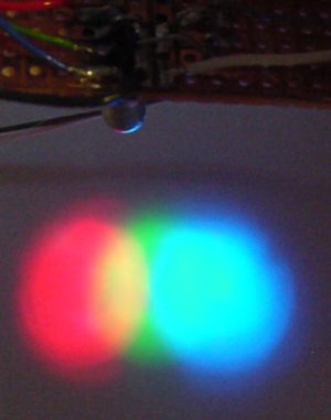
Red, green, and blue light emitted from a single multicolor LED.
For objects up close, the multicolor LED (also called an RGB LED) works pretty well for reducing object-position errors. Unfortunately, as the RGB LED is lifted up, it becomes apparent that the position of the individual color chips within the single lens causes the light sources to diverge. Perhaps this isn’t as much of a problem with other RGB LEDs?
Only two or three complete color readings can be performed per second. The cadmium-sulfide photocell needs time to react to the brightness changes. Blinking the LEDs faster than this rate reduces contrast until all colors result in the same apparent reflective value, as though all LEDs were lit at the same time.
A visible-light phototransistor would provide superior speed. The infrared (remote-control quality) phototransistors I possess are all nearly insensitive to visible light, especially blue. Therefore, infrared diodes and infrared phototransistors won’t work.
At first I thought I could use the “visible phototransistor” from Jameco Electronics (part number 120221, product number BPW77, for $1.99 each). However, the datasheet shows that the phototransistor is 100% sensitive for infrared, 50% sensitive for red, 33% sensitive for green, and even less sensitive for blue. This could be somewhat compensated for by using lower-value resistors on the green LED and blue LED so that they would emit more light.
A better choice is the family of TAOS light-to-voltage converters. Each consists of a fast true-visible-light photodiode and an amplifier in a hobbyist-friendly three-pin package. No external voltage-divider resistor is necessary.
At Mouser Electronics, you can find three major visible-light varieties that trade off speed vs. light sensitivity. (But even the slowest one is 1000 times faster than a cadmium-sulfide photocell.)

Light from an RGB LED reflects of an object and into a TAOS TSL12S-LF light-to-voltage sensor.
The [sloppy] paint job on the RGB LED is to prevent light from going directly to the TAOS photosensor. This sensor arrangement works by have each LED color (red, green, and blue) in the RGB LED turned on one at a time, the light then reflects off of an object, and is read by the photosensor. The next color is turned on, the results read, and so on.
If you stick with a cadmium-sulfide photoresistor, then two complete readings per second may be perfectly acceptable for many applications. This is especially true if each step of the reading task is performed periodically or asynchronously with the other activities of the robot.
Twofold performs the following to initialize the color sensor:
When the interrupt timer triggers:
(Notice that very little work is performed during the interrupt!)
When the sensor section of the main program is entered:
Using this approach, the robot spends no time waiting on the sensor. After three reads, the global variables for red, green, and blue are valid. The variables are continually updated, one at a time, thereafter.