

One of the problems with robot-fighting contests is that extensive damage can be prohibitive to future participation. That is, building a robot is challenging and expensive enough by itself to limit the number of people capable or willing to engage in robot combat. But, the pool of players is subsequently reduced further by the effort and costs of repairs.
Another issue in robot fights is that subjective scoring is substituted if an outright “kill” or “knock-out” doesn’t occur. Neither the judge nor the participants want the event tainted by allegations of favoritism.
A possible solution to address these issues would be a power switch mounted prominently in the front of a robot. The opposing robot need only press the switch to disable the opponent and end the match. No costly destruction need occur.
Of course, this doesn’t mean that there can’t be plenty of clashing for entertainment value. An exposed power button simply provides an additional tactical approach beyond brute force and it increases the likelihood of an objectively-defined victory.
The example robots used on this page are joystick-based with Lego bodies. Both builders assemble ornate structures on the front of the robots, which are then smashed apart during battle. Since these are made of Lego bricks, the forces involved are harmless and the parts can be quickly reassembled without cost.
A round can be scored by the number of bricks dislodged (robots could be weighed before and after, or the parts could be restricted to color-coded bricks). And, with the addition of a power-switch target, a robot can win by default by “power pinning” the opponent. Handicaps could be provided by extra Lego bricks.

A simple joystick-controlled robot with a front-mounted power switch target (labeled Thunder!)
A target power switch is attached to the front of each joystick robot. The contestants usually end up trying to lance the opposing robot’s target while simultaneously defending their own power switch.
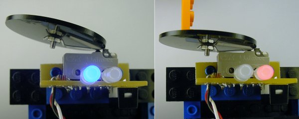
A blue LED indicates the robot is functioning. But, when the target is pressed, a red LED indicates that the robot has been disabled.
The switch circuit includes two LEDs. Normally, a blue LED (or whatever color suits the particular robot) is lit to show that the robot is active. But, when contact is made the switch is depressed and a red LED is lit to show that the robot has been beaten.
The switch not only controls an indicator light, but literally controls the flow of power to the entire robot. The robot and all of its weapons are disabled upon contact. This avoids disputes as to whether the robot really is beaten.
Of course, if the opponent makes only a glancing blow, the switch is released and the robot can resume fighting.
This circuit is very easy to build. It doesn’t require any active components or chips.

Schematic for a power switch target with indicator LEDs.
The heart of the circuit is a snap-action switch. This type of switch usually features a lever arm that makes it very easy to press. Other switch types tend to require a lot more pressure or force.
The snap-action switch includes three terminals.
In the above schematic, power normally flows from the battery pack through the primary power switch SW1, through the common terminal of the snap-action switch, through the normally-closed terminal of the snap-action switch (because it is not pressed) and into the main robot motherboard and blue LED.
When the power switch target is hit, the snap action switch is pressed. In that case, power flows from the battery pack through the primary power switch, through the common terminal of the snap-action switch, through the normally-open terminal of the snap-action switch (because it is pressed) and into the red LED. As the motherboard isn’t connected to the normally-open terminal, it no longer receives power and the robot powers down.
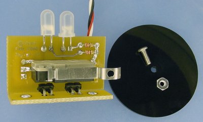
PCB with a snap-action switch with a hole in it, a black plastic disc, a screw, and a nut.
A hole is drilled into the semi-circularly bump at the end of the snap-action switch to screw on a black plastic disc. A nut is required behind the hole because the switch lever arm is made out of metal that is too thin to be able to tap for screw threads.

Left: Delrin disc being machined on a rotary table. Right: Snap-action lever arm held with two parallels for drilling a hole.
The target shield disc is machined out of black Delrin/acetal plastic on a rotary table on a milling machine. Delrin plastic is flexible and tough. It should be rugged enough to survive endless battles.
Unlike metal, a plastic disc won’t cause electrical shorts if it presses against exposed electronics. Also, the plastic edges aren’t going to be sharp enough to cut wires or fingers. Additionally, Delrin plastic is not malleable -- meaning it springs back instead of incurring a permanent bend like thin metal would.
The metal arm of the snap-action switch is more difficult to drill that it would otherwise appear. It is difficult to hold in a vise. A special fixture could be machined to hold it securely, but I resorted to grasping it between two parallels.
The circuit board needs to be mounted vertically because of the position of the level arm on the snap action switch. It would be possible to mount the PCB to a Lego brick behind the board. However, the back of the board has the primary power switch and wires from the battery pack and motherboard.
It would also possible to use the screw holes on the snap-action switch itself. But, in this layout, the LEDs get in the way.

Joining printed circuit boards at right angles using right-angle headers.
Here’s a trick I learned from Dave Hrynkiw at Solarbotics.com. Solder right-angle headers to mechanically affix circuit boards at 90° angles. You can even make a box or cube shape using this technique.
The headers can carry electrical signals if desired. Or, they can act purely as mounting brackets.
A single-row strip of 36 right-angle (R/A) connecting headers with 0.1″ spacing is $1.82 from DigiKey (#929835-01-36 or 929835E-01-36). They’re called “breakable” headers because you can snap them apart or cut them with snips to create smaller groups, such as a pair.

The circuit board mounts to a Lego block with tapped holes using blue anodized socket-head cap screws.
With the mounting PCB held in place by the soldered headers, the combined PCBs can be screwed onto a Lego block. The Lego block has holes drilled and tapped in the same manner as the rest of the joystick robot.
Since this power-switch design is a prototype, it is a good choice to use Lego bricks because the brick’s position on the robot can be easily rearranged during experimentation.
The switch works fine. But, there are a number of features and improvements that could be made.
In the present design, the prototype power switch has all of the robot’s power flowing through it. Unfortunately, larger robots use more current than most inexpensive switches can handle. The solution is to use a smaller current through the physical switch to control a relay or power transistor.
Another limitation of the prototype is that the snap-action switch is too delicate except for use on fairly low-power robots. A more rugged switch could be constructed using a spring-loaded cylinder arranged as a push-button, with an optical sensor detecting the movement so as to be a little more solid-state.
Finally, the power switch could be made more intelligent by adding a tiny microcontroller to count hits. Or, a microcontroller or logic chip could latch the robot into a power-off state rather than restoring power to the robot when the opponent backs away. I suppose a microcontroller-based switch could even power down the robot for a short period of time (like 15 seconds) so that the press would act as a penalty rather than ending the match.