

Years ago, at one of the first ChiBots meetings, I recall that each person introduced themselves by saying “My name is so-and-so. I’m pretty good at software and/or electronics, but I hoping to learn about the mechanical stuff.”
Although I’m hardly a master of machining, I’ve finally become good enough to make practical parts for my friends and tools for myself.
One of my good friends, Tom O'Toole, decided to go to medical school. Although he could have used the cash, I instead chose to make him a parting gift. How thoughtful of me!
Tom has a Chevy Cavalier. Before you make fun of that, consider his wisdom in buying an incredibly long extended warranty. General Motors will need to keep fixing his car until the United States makes the switch from gasoline to hydrogen, fusion, or maple syrup. After that, he should be making enough money to afford a BMW.
Tom’s last splurge before school was to purchase a satellite radio. The radio car kit includes a suction cup for mounting the radio to the dash or other flat surface. But, Tom didn’t want the radio to obstruct his view, nor did he believe the suction cup was sufficient to keep the radio from coming off when he pressed the buttons.

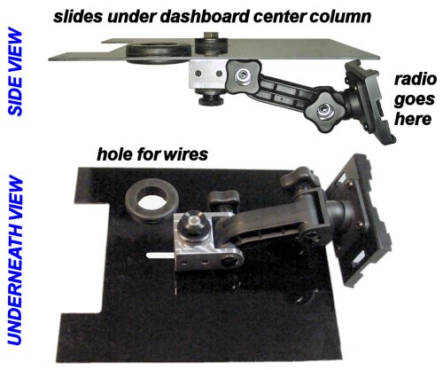
Satellite radio positioned underneath dash using a custom bracket.
Tom asked me if I could create a substitute bracket to bolt the kit arm to the underside of the vehicle’s dash in the center column. Not only would this place the radio in a normal location and provide greater attachment than a suction cup, but it also would allow all of the wires to be out of view.
When selecting a material for this project, I considered the following requirements:
Brass would have been fine, but a little heavy. Certain high-quality plastics are suitable, but might break under use. Steel would rust. Stainless steel would have been too difficult to machine. Aluminum is a good choice.
I selected Fortal aluminum (similar to aircraft aluminum 7075 T651) because it is the strongest aluminum and easier to machine than some alloys. I purchased a hobbyist assortment box from Scott Krezinski at fortal.biz. It’s a selection of shapes and sizes of industry cutoffs for much less than the retail cost.

Bolt mount to replace a suction cup mount on a stock satellite radio car kit
Except for the preference to avoid using a suction cup, the satellite car mounting kit is ideal and well made. So, it doesn’t make sense to discard any other parts. This means the homemade bolt bracket needs to have one end shaped to match the rest of the kit.
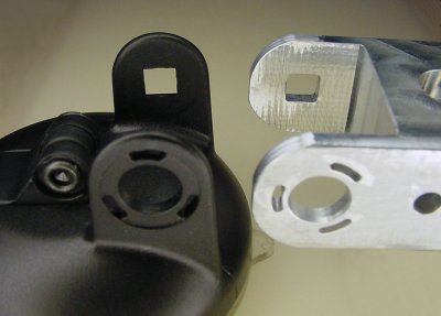
Square hole and arcs in satellite radio bracket
Unfortunately, a square hole and a hole surrounded by three arcs are not simple manual machining operations. But, they can be reproduced with the right tools.
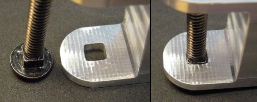
Square bolt hole in satellite radio bracket
To create the square hole, I first drilled out the center. Then I dropped in a small-diameter end mill (1/16) to square out the corners.
Fortunately, like some other hobbyists, I installed calipers to each axis of my milling machine to create an inexpensive digital readout (DRO). To make the square the correct size, I simply had to precalculate the position of the end mill (less the radius of 1/32) for each corner to avoid overshooting a side during cutting.
The 1/16 end mill provided adequately sharp corners. If I had needed to square the corners even more, I could simply use a triangular or square file after that.
As you can see above, the original bolt drops in cleanly.

Disc with arcs that snaps into hole on bolt bracket
Next comes the three little arcs. A plastic disc snaps into the hole and arcs. The other side of the disc (not shown) has grooves to grip the arm and prevent it from slipping out of position during use. At one point, I considered ditching the disc and just using a compression washer or something similar. But, that would be lame.
The first difficulty in recreating the arcs is measuring them. I’m accustomed to measuring rectangular objects or round holes with calipers. How was I going to accurately measure and reproduce a series of arcs?
The answer was to take a digital photograph of the disc, load it into a drawing program (Microsoft Visio), and scale it until the center hole on the photograph in the computer matched the diameter of the real hole as measured by a caliper. Then I could draw digital circles, lines, and arcs over the photograph and see the actual sizes, coordinates, and angles in Visio.
[Babbling continues...] I centered a rotary table on the milling machine using a dial test indicator. The center of the hole in the bolt bracket was mounted to the center of the rotary table. Looking at the milling machine caliper display, I then moved the milling table horizontal axis the radius of the circle formed by the arcs according to Visio. I plunged in with a 1/16 bit and rotated the rotary table the angle indicated by the arcs in Visio. I pulled up the 1/16 bit and rotated to the angle of the next arc, and continued until all three arcs were cut.
Completed satellite radio car mounting bracket bolted to Garolite
Tom didn’t want any holes drilled in his precious car (may I remind you it’s a Cavalier). So, he requested a panel be constructed that would slide into the 1/16 inch grooves that already existed in his automobile.
I purchased a couple of different boards to test out: Garolite (G-10/FR4), Delrin, MDS-filled nylon, and polycarbonate. The Garolite (85345K611 McMaster-Carr) was by far the stiffest. It is flame retardant, which is important since this is near the car’s floor heater vent. Garolite is epoxy-coated fiberglass commonly used in circuit boards.
To protect the radio wires from the sharp edges of the Garolite hole, I installed a 1-inch rubber grommet (9307K61 McMaster-Carr).
To finish off the project, I used an entirely extravagant titanium bolt. There is no engineering reason for doing so, but I hear titanium parts make a car go faster. ;)
The next project was for me. I solder and desolder a lot of small circuit boards.

Textured vise jaws have a poor grip for printed circuit boards
I purchased an inexpensive, small vise to hold boards. Unfortunately, the uneven hammered finish on the vise jaws is bad at holding a circuit board, especially if you’re tugging on a part. The board and all of its unsoldered parts fall to the ground.
If you over-tighten the vise to compensate, the relatively thin PCB bends or rounds out, and everything falls to the floor again. Not good.
I could have scraped off or milled off the jaw finish on the vise, but the exposed metal would likely rust. Furthermore, I’m not sure that even a plain jaw would adequately hold a PCB in place.

Standard vise (left) and aluminum jaws with grooves for PCBs (right)
I decided to add some aluminum jaws with horizontal and vertical slits to hold printed circuit boards. I chose aluminum because it is corrosion resistant (unlike steel) and is difficult for solder to adhere to (unlike brass). I chose Fortal aluminum because I had a big box of it and it is hard enough to stand up to daily use without the grooves getting worn down.

Transfer punch marks holes for drilling
After machining an aluminum jaw, I placed it onto a vise jaw and marked the locations for screws using a 1/8 transfer punch (3374A14 McMaster-Carr).
I use #4-40 screws. The clearance (non-threaded) hole size for a #4-40 screw is 1/8 inch. Unlike standard center punches, a 1/8-inch transfer punch has a 1/8 diameter, of course. So, the punch is a perfect fit for centering in the clearance holes for #4-40 screws. (Transfer punches are available in a variety of diameters to match most drill bits.)
When you whack the punch with a rubber mallet, the pointy tip leaves a centered mark to guide you and the drill.
It is best to mark one hole, drill it, tap it, and screw on the part before marking the next hole. Otherwise, if you mark all of the holes at the same time the part may slip or move during marking, and the holes won’t line up.
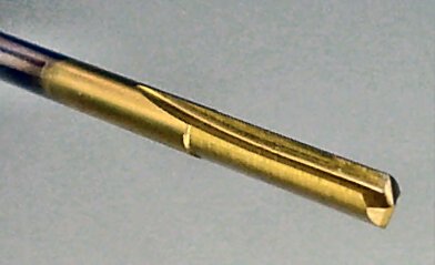
Special straight-flute drill for tough materials
A vise is usually made out of a strong material like steel or cast iron. It may even be hardened.
To drill a hole in a hard material, you may want to use a special drill bit. For #4-40 screws, I use a #43 diameter, 135 degree split point, solid carbide, TiN coated, straight-flute drill (8882A682 McMaster-Carr).
The solid carbide point stays sharp and the straight-flute drill shape more easily transfers the pressure to the tip. That being said, I actually broke one of these special drills while drilling a hole in the vise. But, truth be told, that’s because I was using a hand drill and looking away at the TV playing Cartoon Network. I’ve drilled plenty of holes with this type of bit and this is the only one I’ve broken.
You don’t have to go very deep for a screw to be secure. In fact, some studies have suggested that the first three threads of a screw take almost the entire load. Another tip to avoid breakage is to use cutting oil to reduce friction and clear away chips.

Horizontal and vertical grooves in aluminum vise jaws firmly hold a printed circuit board
After securing the jaws, the vise now does a great job of firmly holding a printed circuit board in either a vertical or horizontal orientation.
My brother has a fancy water dispenser beside his normal faucet at his kitchen sink. It’s a filtered drinking water dispenser with an instant heater.

Broken compression nut on sink water line
Unfortunately, the nut that compresses the water line connection is poorly designed. The rear of the nut is too thin and eventually splits off. This causes the line to separate under the water pressure and to quietly leak underneath the kitchen sink. That’s a really pleasant surprise.
Apparently he’s had to replace the nut several times.

Replacement compression nut made from Delrin
I had several choices for materials since the nut does not make contact with drinking water. I wanted to avoid steel in the humid and chemical laden environment underneath a kitchen sink. Brass is usually a good choice.
My brother wasn’t quite sure of the correct thread size. Since the male-threaded end was made of plastic, I didn’t want to damage it by screwing on a non-matching nut made of metal. So, I chose to make the nut out of Delrin (acetal) plastic. (By the way, on the second try we figured out the correct thread size was a slightly obscure metric 20 mm x 1.5 mm as opposed to our first guess of 3/4-16.)
Cutting hexagonal sides in a rod round
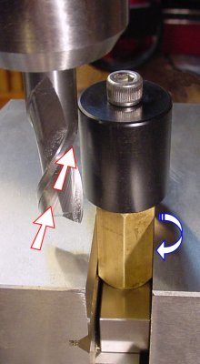
I wanted to make a hearty nut that wouldn’t break. There was plenty of room to make the rear of the nut thicker. However, the outside diameter is limited by a nearby part where the nut screws on.
In order to make the thickest walls possible, but still allow the nut to be installed tightly, I chose to make the nut from a round rod and add hexagonal sides. If I had used hexagonal stock to start with, the walls would have been fairly thin. By cutting my own sides, I could cheat and not make them very deep.
To make hex sides somewhat accurately, I mounted the nut’s round rod onto a narrower diameter hex rod. Since there is only a single center bolt holding it on, I milled each side slowly and carefully to avoid it unscrewing. After one side was done, I simply loosened the vise and rotated the hex rod to cut the next side (and so on).
Cool trick, huh?
I was helping Iain Grant diagnose a very peculiar problem on his Roundabout robot. He had done everything correctly to hunt down a delayed short-circuit, but we both gave up and he sent the robot to me for examination.
It turns out that a tantalum capacitor was backwards and was shorting out after a few seconds of heating up. Because he had properly protected the circuit board power supply with a resettable fuse, it prevented the capacitor from catching on fire or exploding. However, that meant the backwards capacitor continued to live on and haunt him.

Lego compatible coupler for Solarbotics robot motor GM19
I was impressed with his dedication to building a Roundabout robot and I wanted to encourage him with a gift when I returned the circuit boards. I noticed he purchased “GM19 - 35:1 High Power Mini Metal Gear Motors” from Solarbotics. So, I made him a pair of couplers to connect the motors to Lego wheels.
The GM19 motors are probably too fast when connected to a 7V to 9V power source like Roundabout uses. I selected the smallest diameter Lego wheels I could find to try to compensate. However, I suspect Iain will need to use these motors on a lower-voltage robot.

The end of the coupler is beveled to avoid rubbing against screw heads on the motor gearhead
The coupler was made on my mini-lathe, which makes it a lot easier to make cylindrical objects. The #2-56 setscrew is smaller than my standard #4-40, because I wanted this coupler’s size to be proportional to the small motor.
Rather than using epoxy to secure the Lego axle, I find you can drill the hole a little small (#11 drill) and press-fit (force) the axle in place using a vise or arbor press. I doubt any small motor can generate the torque necessary to strip out the axle.
Lastly, the coupler end was beveled (rounded) so that it could fit all the way onto the shaft without rubbing up against the gear head screws.
I have written up instructions on how to make couplers on a lathe.
Speaking of the mini lathe, I purchased one last year from MicroMark (#82710) and I’m pretty happy with it.

Homemade carriage lock for MicroLux lathe
One conspicuously absent feature is a carriage lock. When you are making a facing cut to clean up the end of a rod, the force pushes the carriage backwards. This results in a convex end (rounded bulge in the middle) rather than a flat end.
There are lots of designs out there for making your own carriage lock. I’m not quite sure of the generational origin of my carriage lock design. It is directly modeled after Bill Johns’s at Gizmology. However, mine is on the tailstock side, similar to John Moran’s at Gadget Builder. Apparently his is based on a design from Mike Walsh.
If you don’t want to make your own, I notice that Little Machine Shop now has a nice one available for about $30 (part #2977).

Turning the hex key pulls the pieces together for multiple points of contact
I selected this particular branch of carriage lock design because many of the other designs use only a single point of resistance on one side or they lift the carriage. I wanted a multi-point downward compressive force in the center of the lathe carriage.
When you tighten the bolt, the top portion and bottom portion are pulled together. This causes multiple points of contact to resist movement of the carriage.
One could argue that pulling the carriage down is not optimal either, and that the lock should not disturb the position of the carriage at all. However, I wanted the carriage lock to be able to secure the carriage in either direction whether I were right-hand facing or turning a left-hand corner.

Hole locations for carriage lock on mini-lathe
To accomplish this, I chose to screw the carriage lock onto the carriage itself. Except perhaps by some really elegant design, this necessitated either a downward or upward force on the carriage. Since gravity is already pulling down, I figured this was the lesser of two evils.
The screw holes are drilled using the same transfer punch and straight-flute drill that I used on the aluminum PCB vise jaws (earlier on this web page). The holes are then chamfered slightly with a countersink, then tapped, blown clean with compressed air, and then oiled.

Brass carriage lock for a miniature lathe with some clear and some threaded holes
I made the carriage lock out of brass, which is softer than steel, because the sides of the bottom piece rub against the steel lathe ways when unlocked. I want the easily-replaced carriage lock to wear rather than lathe.
There are two smaller (#4-40) screws, one on each side, that attach the upper portion to the carriage.
There are two larger screws (1/4-20) in the center. One is a flat head recessed into the upper body to keep it out of the way. Its job is to prevent the bottom piece from rotating. Most people make a nice rod, but I cheaped out and used a screw.
The other screw is the one that is actually tightened to pull the pieces together. There is a washer between the screw head and the top piece to spread the load and take some wear. It is easier to replace a washer than to remake the piece.
To make all the screws work, you need to know when to thread something and when to allow a screw to pass through a hole (clear/clearance). Basically, if you threaded both sides of a piece, the threads would try to keep the pieces at the same distance from each other when the screws are turned.
The middle potions of the carriage lock are made thicker to resist bowing or bending when the screw is tightened. The thick portions don’t actually make contact with each other or the lathe ways.
On this final project, I made Dan Schwimmer some brackets to allow him to install a child safety gate on his stairs.

Child safety gate attached to a board at the edge of the baserail
At Dan’s house, the baserail protrudes enough from the baluster such that it blocks the side of a child safety gate from reaching it. The solution is to connect a flat board to the top baluster so that the child gate can be attached.
Additional boards can be added and held in place with washers and nuts if the gap between the baluster and the gate board would permit a child’s head to get stuck. Additionally, the exposed bolt threads can be covered by a simple tube.

Baluster clamp with bolt and washers to connect to a flat board
The baluster clamps are made from solid Fortal aluminum. Brass also would have been acceptable, except free-machining brass contains lead. This would probably be an insignificant health hazard even if the kid licks it, but why take a chance?
The clamps are exceptionally thick to ensure they are not the weak point in the system should someone fall against the gate. The 1/4-20 bolt has washers and nuts to secure the board.
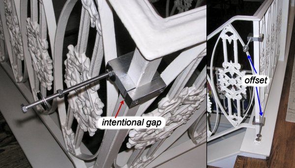
Installed clamps have an intentional gap and are offset for increased horizontal rigidity
When installed, the clamp should have slight gap between the aluminum jaws. This indicates that the fully tightened clamp jaws are actually squeezing the baluster between them, not simply pressing against each other.
By horizontally mirroring the orientation of the two clamps, the bolts are offset and the setup gains rigidity.

Ahh, you can almost sense the disappointment
The fully installed gate successfully withstands the mighty onslaught of even the cutest child.