

This board derives from an electronic tachometer created a few months earlier. Nearly all of the features of that earlier project are included in this version, so refer to those pages to see all of the capabilities.

Tachometer and temperature gauge circuit board
I designed the portable tachometer for Brian and Bren3dan’s BattleBot.

Click to see a movie of the tachometer circuit in action.
The guys want to use four, 4-inch LEDs to display the blade speed.

Notice the LED’s decimal point is nearly the size of an m&m’s candy!
Unfortunately, upon receiving the LEDs, I discovered they required between 6 and 9.6 volts to light. My prior board only supports the usual 1.5 to 2.5 volt LEDs. So, I built a new board.
I couldn’t find connectors for the back of the LEDs, so I soldered wires to each pin and brought them out to Molex KK connectors. Color shrink-wrap tubing of green, yellow, red, and blue indicates the left-to-right order each digit should be connected to the bottom of the board. Since each digit is wired identically, no damage would result from misconnection -- just a disordered display.
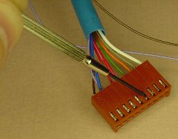
Molex KK connector for LEDs
Sometimes a segment of an LED fails to light. Usually the cause is a connector pin that isn’t making full contact. Wire removal is accomplished by using a tiny screwdriver or other small point to push in the tab of the connector terminal while simultaneously pulling gently on the wire.
With the wire removed, the terminal end can be reshaped so that it exerts a little more pressure on the pin upon reinsertion.

Without polarizing ribs (left) and with polarizing ribs (right)
Each type of connection to the board uses a different size Molex KK connector to prevent a potentially harmful mix-up. Each connector has a locking ramp to hold them in place and polarizing ribs to prevent them from being inserted one or more pins to the left or right.
Unfortunately, I didn’t have any polarized six-pin connectors, so that connection must be performed with more care.
Every wire on each connector has a different color. The connections for each wire are labeled on the board. This little bit of attention to detail greatly eases soldering, maintenance, and modification.
Although not currently encased in a box or attached to anything else, the board has four, 4/40-size screw holes already threaded and ready to be used.
To provide higher voltage, the LEDs are now driven by transistors. 2N2222 NPN transistors would have been fine, but the junk pile yielded a batch of MPSA06 amplifiers. They’re being driven into saturation to act as switches, instead of amplifiers.

Numeric LED transistor drivers
When designing the board, I hadn’t properly planned for enough space for the transistors to sit beside each other. Oh, well. Stacking the transistors in two tiers of heights allowed them all to fit.
One of the numeric LED segments, the decimal point, is a single LED at 1.6 volts, rather than a batch of 4 or 8 LEDs that drive each of the other segments at 6 to 9 volts. One of the resistors (the blue one, sticking up) is of a higher value for the decimal point so that the current going through each segment is the same, hopefully keeping the light output equivalent.
For testing purposes, a smaller and less voltage-intensive display can be used.

Unregulated (12 V) and regulated (5 V) display jumper
When the red jumper is in the “Hi” position, the full, unregulated voltage is used. Resistors were chosen such that a voltage between 11 and 13 volts is expected. A voltage lower than 11 would result in a dimmer or unlit display. A voltage higher than 13 would result in a brighter display -- possibly destroying the LEDs.
When the red jumper is in the “Lo” position, the 5-volt regulated voltage is used. Only the decimal-point segments of the large LEDs would light in this setting, so only a smaller, standard voltage LED display would be useful. Another downside to this setting is that the 7805 voltage regulator must supply the current. Although the 7805 can handle it, the regulator will heat up quite a bit when supplying half an amp for a fully-lit 8-segment, 4-digit display.
The board and display are designed to be powered by a 12-volt battery. The positive side of the battery connects to a white wire and the negative (or ground) connects to a black wire.

Power switch, connector, indicator, and current-test jumper
When the power switch is turned on, a red LED lights up.
A black jumper is available near the power switch for connecting an ammeter for measuring current. During normal usage, the board won’t work without the jumper in place, so perhaps the current jumper and the display-voltage jumper should be secured with glue before battle.
The remake (of the original tach board) resulted in trying a few new techniques. The most significant change is that the photosensor and light/dark potentiometers now connect to a comparator chip. In this case, an LM2901.

This relieves the greatest burden from the microcontroller, a MC68HC908KX8. In fact, the processor speed has been reduced by a third (8 MHz to 2.4 MHz) yet the display refresh has increased at least tenfold.
Initially, there was a serious problem determining speeds or counting at less than a few-hundred RPM. It turned out to be a bug in the code. On the HC08 chips, when using interrupts for input capture, the control and status register must be read before clearing the capture flag. Why? I don’t know -- the book just tells me so.
A canned oscillator clock drives the microcontroller instead of the built-in clock generator. It may be a more accurate reading, but I don’t have calibrated test equipment to know for sure.
A standard ultra-bright LED emitter and visible-light phototransistor are arranged as a reflective pair to detect light to dark changes on the rotating surface. The sensor is covered with black heat-shrink tubing for moisture/grime protection.
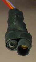
Emitter and phototransistor
Because the tachometer uses optics, rather than physical contact to measure rotations, it is considered a non-contact tachometer or an optical tachometer.
Unlike the earlier model, the new digital tach board supports both single and quad sectored surfaces. In quad mode, four bright and four dark areas appear on the measured surface and the RPM is computed accordingly. Interestingly enough, the quad timing is less consistent because of slight differences in hand drawing the dark areas.
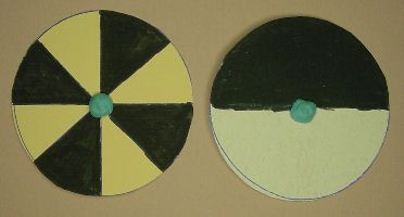
Quad and single reflective disc
The blue spot in the middle of the discs is malleable (squishy) poster tack. Like rubbery clay, it holds the paper discs onto the motor shafts during testing.
A significant improvement is the addition of a potentiometer for setting the point at which the digital tachometer display automatically switches over to temperature display. The prior version had a hard-coded value.


Left: Potentiometer to adjust maximum temperature. Right: Thermistor.
The hot mode is important to a battling robot, as motors tend to heat up quite a bit. With the temperature probe against the motor or exhaust, the display can warn the user to ease up a bit.
When in the hot state, the temperature in Fahrenheit is displayed with a little 'h' instead of 'F'. Pressing the button immediately returns the display to tach mode. Or the display eventually returns to tach mode when the temperature decreases to 10% below the hot point.
The temperature probe, a thermistor, is covered in blue heat-shrink tubing for minor moisture/grime protection.
Four dipswitches and a pushbutton determine what is displayed. (Actually, the third dipswitch isn’t connected.) It’s perfectly fine to change dipswitch modes while power is enabled. In fact, text describing the new mode briefly scrolls across the display.


Left: Mode-selection dipswitch. Right: Temporary-selection pushbutton.
The pushbutton temporarily toggles to an alternate mode so long as the button is held down. Remote button pushing can be achieved by connecting the brown and green wires coming from the six-wire sensor connection. Brown is just ground, so really the green wire is being grounded.
| Dipswitch | Normal | Button Pushed |
| oooo | Tachometer | Temperature in Fahrenheit |
| ooo4 | Quad Tachometer | Temperature in Fahrenheit |
| 1ooo | Temperature in Fahrenheit |
Overheat potentiometer temperature in Fahrenheit |
| 1oo4 | Temperature in Celsius |
Overheat potentiometer temperature in Celsius |
| o2oo | Counter | Clear counter |
| o2o4 | unused | unused |
| 12oo | LED test (“8.8.8.8.”) | Character set test |
| 12o4 | Version number and date | Copyright notice and plug |
The microcontroller failed to power-up about half the time. Toggling the power switch off and on brought about correct operation.
At first I suspected the microcontroller’s dip socket. (In fact, I had actually damaged a few pins by jamming in jumpers during development.) I desoldered the socket and replaced it with a new one.


Left: Drop below ground during power up. Right: Surge above regulation during power up.
When that didn’t solve the problem, an oscilloscope was used to examine power on startup. I was shocked to see voltage dropping below ground and above regulation (5 volts) during power up! I desoldered the voltage regulator and a capacitor and replaced them with different components.

These poor parts got blamed. They weren’t bad, but after angry desoldering, they are now.
That didn’t help either. I reflashed the microcontroller with code from the earlier tachometer and tried it in the earlier board. It worked fine. I swapped the original microcontroller from the earlier board and the problem remained. Because the microcontrollers were from different batches, that pretty much ruled out the microcontroller chip as the source of the problem.
It took several days worth of this kind of experimenting to finally discover the problem. It was a bug in my code when switching from the internal clock generator to the external canned oscillator. The routine would get stuck in an infinite loop (and clearing the COP, tsk. tsk.) if the internal clock had locked before my routine got called. A few ANDs and ORs solved the problem.
In recent years I realized the spikes were false. They were actually a problem with the Fluke oscilloscope.

Six-digit version of the second-generation tachometer.
The tachometer circuit board is a pain to build because of all the holes to drill and resistors to solder. Even so, I created yet another one, this time with six standard-size LEDs. For debugging, I added an old blue LED I had lying around.
Targeting a Dremel Moto-Tool, the optical tachometer measured 23,000 RPM without breaking a sweat! However, the electrical noise from the tool made the output almost unreadable. Winding the sensor leads in a toroidal coil didn’t help.
The board can display up 999,999 in counter mode. The picture above shows 136,168 -- a count, not RPM.
Yes, the use of a comparator chip (along with the other changes) makes this a big improvement over the last board. It’s likely more accurate and precise, and definitely has far greater resolution.
I’m concerned about electrical noise from the motors falsely triggering the microcontroller inputs. It appears to be an issue, and it wasn’t an issue in the earlier ADC design. I should have built some hysteresis into the comparator inputs. The board should be encased in a metal enclosure to help dampen electrical noise. Additionally, the board’s batteries should be separate from motor’s batteries.
Despite noise concerns, the board appears to meet the needs for which it was intended.

Click to see a movie of the start-up message.