

Most of this website is devoted to active semiconductors and electronics controlling DC motors. For example, many of the robots have microcontrollers that drive motor direction through a transistor H-bridge. However, sometimes you want a very basic solution where a person can directly operate a motor with a flick of a switch. This can be easily accomplished.
Parts List:
The first thing you need to test is the battery and motor. This will eliminate any problems with them before you add the complexity of one or more switches to the circuit. These tests are easiest to perform with alligator clips, if you have them.
Forward and backward motor and battery wiring diagram. A red wire is shown because a white wire won’t show up on a white background.
If the motor doesn’t turn, check the connections. It could also be that the battery voltage is too low or the battery is dead. If the motor turns too fast, trade down to a lower voltage battery or get a motor with a gearhead.
You must have a motor and battery that passes steps 2 and 3 of the test before continuing.
Obviously you don’t want to have to rewire your motor every time to turn it off or change directions. We’re going to let the switch do that. Inside the switch there are metal strips that either connect the wires or disconnect them, as the lever is flipped back and forth.
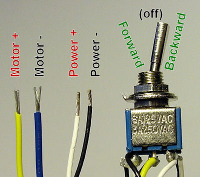
Wiring and toggle switch.
Here are the wire assignments:

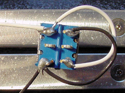
Solder the white (power positive) wires to the DPDT switch.
1. Connect the white wire (positive power) to the DPDT switch as shown above. You'll need one long piece of wire coming from the battery to the first switch terminal. And, you'll need a smaller piece of wire coming from the first switch terminal to the opposite terminal as shown.
Solder the black (power negative) wires to the DPDT switch.
2. Connect the black wire (negative power) to the DPDT switch as shown above. You'll need one long piece of wire coming from the battery to the lower switch terminal. And, you'll need a smaller piece of wire coming from the lower switch terminal to the opposite terminal as shown.
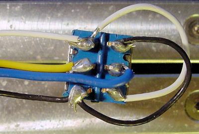
Solder the yellow and blue motor wires to the DPDT switch.
3. Connect the yellow and blue wires from the motor to the center terminals of the DPDT switch as shown above.
4. Connect the yellow and blue wires to the motor terminals.
5. Make sure the switch is in the center (off) position, before connecting the battery.
6. Connect the white and black wires to the battery.
Wiring can be a bit of a pain. You can use a small printed circuit board instead (particularly if you're going to wire more than one switch).
DPDT Motor Switch PCB
Let’s step through what happens when you flip the switch to the top, center, and bottom...

Lack of connections in a DPDT switch, resulting in a turned-off motor.
When the switch lever is in the middle position, the motor is off because the metal inside the switch is not connecting the wires from the middle terminals (the motor) to any of the outer terminals (the power source). This is the same as if you simply disconnected the wires to the battery. Nothing will happen. No power is being used.

Connections in a DPDT switch, resulting in a motor going forward.
When the switch lever is in the top position, the motor rotates forward. If your motor rotates in the opposite direction than you expected or wanted, simply reorient the switch in your hand so that lever is facing the bottom, and then toggle the lever to the top. Alternatively, you could swap the wires on either the battery terminals or the motor terminals.
Inside the switch, the lever has pushed metal strips such that the motor wires on the middle terminal are electrically connected to one pair of the outer terminals leading to the battery. The term “double pole” refers to that fact that this switch has a pair of terminals that it connects or disconnects at the same time. If we only needed a single wire to be connected or disconnected, we could use a single pole (SP) switch.

Connections in a DPDT switch resulting in a motor going backward.
When the switch lever is in the bottom position, the motor rotates backward.
Inside the switch, the lever has pushed metal strips such that the motor wires on the middle terminal are electrically connected to the other pair of the outer terminals leading to the battery. Notice that the black and white battery wires are on opposite sides on the top and bottom switch terminals. That’s why the motor rotates in the opposite direction.
The term “double throw” refers to that fact that this switch can be thrown to the top and thrown to the bottom (two different throws). If we only needed the motor to go forward or turn off, we could use a single throw (ST) switch.
If your motor doesn’t operate correctly, double check that the wires go to the correct switch terminals. Also, make sure the wiring isn’t loose or broken. Use a magnifying glass to make sure not even a tiny strand of wire is accidentally touching another wire or terminal.
Being able to control a motor directly is useful. But, sometimes you won’t be paying attention and the item connected to the motor will crash into a barrier or otherwise exceed its maximum position.
It would be nice to add a couple of additional switches to automatically stop the motor when it has gone too far, but still allow the operator to return the motor to an allowed position.

Wiring diagram of a DPDT connected motor plus two snap-action switches for user control with limit stops.
The wiring diagram above is similar to the ones shown earlier. Two additional switches have been inserted. One switch connects (or disconnects) the white wire on the bottom terminal. The other switch connects (or disconnects) the black wire on the top terminal.
Snap action switches have been put to good use in my Flip-Flop robot. If you’re not familiar with those types of switches, take a quick look at the pictures and watch the video.
The idea is that each snap-action switch is wired such that their respective wire is normally connected (NC) just as it was in earlier diagrams. This allows the user’s DPDT switch to operate as usual.
However, when something presses against the snap-action switch, it disconnects the wire, cutting off power in that direction only. If the user throws the lever into the opposite direction, the other snap-action switch is not being pressed against, and so it allows the motor to reverse.
If you mounted a motorized device on a linear (straight) track and placed each snap-action switch on opposite ends of the track, you could throw the switch in one direction and the device would automatically stop when it reached the end of the track. You could then throw the switch in the opposition direction, and the device would proceed to the other end of the track before stopping.
Similarly, you could add a pin or arm to a disc, which would press against a snap-action switch when the motor shaft rotated to the desired angle.
This article demonstrates how to change directions on a small motor from a consumer battery source using a DPDT center-off switch. There are many uses and variations for such a circuit.
It is possible to use more powerful motors and greater power sources. The biggest limitation will be finding a physical switch that can handle enough current and voltage. You must be sure that the manufacturer rates the switch for at least the maximum power you intend to use.
In fact, a superior design would be to connect a low-rated switch with a weak power source to a relay with a higher power source. A relay is a magnetically-activated switch that acts as proxy, echoing what the user is doing with the lower-power switch.
Over time, a switch connected to a large motor or power source will burn out due to electrical arcs when making or breaking electrical connections. Another concern with large motors (particularly when hooked up to equipment) is sudden starting and stopping. Momentum can be a killer. Speed controls or digital pulse-width modulation techniques can gently ramp up or ramp down hefty motors.
Overall, the most serious concern with large motors or significant power sources (such as AC outlets) is safety. That’s why these things should be left to professional equipment with the proper enclosures, redundant limit sensors, and independently certified testing.
That being said, this DPDT switch should work comfortably with small DC motors and battery sources, such as in models, toy trains, and hobby robots. To learn about intelligent motor control using semiconductors (transistors), see Chapters 9 and 10 of Intermediate Robot Building or look through the many articles on this site.