

Exposed PCBs may be acceptable for circuitry that requires constant access by a technician, such as a chip programmer board. Most other circuit boards should be enclosed in some sort of project box to prevent dust or damage. However, there are a few rare projects that are used in a highly visible manner, such as in a showcase or common area, that they deserve a decorative case or ornamental face plate.

Electronic controls faced with a fancy solid brass plate with solid brass buttons.
Such was the occasion for the Dual Fan Pro project that I made as a gift for my brother. The dual fan controller cools his home computer that is stored inside of a kitchen cabinet. The display and pushbuttons needed to be presentable as they would be visible to guests in their kitchen.
The article describes how the brass face and pushbuttons were made from thick pieces of brass stock.
The machining process actually begins on a computer. The design for the display slot, screw holes, and button placement is laid out in a drawing program (Microsoft Visio). This makes it easy to confirm fit and size before cutting into pricey metal.
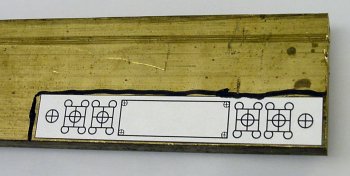
Tracing a CAD printout with a black marker on raw material.
After printing out the paper template, the design is placed on a piece of brass plate stock. In this case, the brass stock is slightly more than 5/16-inch thick.
A rough outline is traced around the paper template with a Sharpie black marker to guide the rough cut. I’m not that accurate with a hacksaw, so I tend to use a wide margin on my template outline. Although this means there will be some waste and some extra machining to reach the final dimensions, it is better than leaving too little room and accidentally cutting into the finished area.
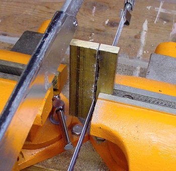
Cutting brass stock with a hacksaw.
With the raw metal stock held in a vise, the hacksaw cuts away the outline. As pictured above, the orientation of the brass stock in the vise is not preferable, as the hacksaw tends to wander and it will leave an uneven edge. Unfortunately, due to the length of the stock, it was not possible to grip the metal flat in the vise.
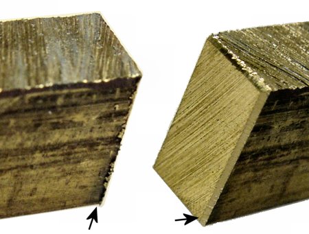
Left: Corner burrs prevent stock from lying flat in a milling vise. Right: Grind or file the corners before milling.
Hacksaws are considered roughing tools. And, as you can see, the brass workpiece is pretty rough at this point!
A milling machine is considered a precision tool. However, before the workpiece can be placed into the milling machine vise, the corner burrs (metal fragments) need to be removed. If the burrs are not removed, the piece won’t sit flat and flush in the vise, and more time and material will be spent getting all of the sides to be at right angles to each other. And, you may cut yourself on the burrs when handling the rough workpiece.
Therefore, use a fine metal file, sandpaper, or grinding tool to clean up the roughest corners before machining. The edges don’t need to be perfect -- just make sure that extraneous material doesn’t interfere with how the workpiece rests in the vise.
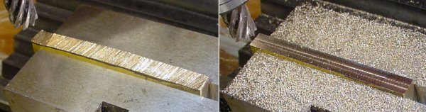
A milling machine removes the jagged top from the brass workpiece.
Depending on how uneven the side is, and depending on the material being milled, it is usually best to start a little high and machine off the tops of the metal mountains rather than trying to obtain a completely flat side in a single pass. An excellent method for breaking an end mill or for flinging a workpiece out of a vise is to aggressively attack a rough edge with a single deep pass! Trust me, you'll have much better results and longer tool life by making multiple passes.
I try to make sure each edge gets at least one clean milling pass before trying to cut the piece down to the exact dimensions. That way, all scratches, bumps, discolorations, and non-square angles are removed. After making a nice clean workpiece on all sides, then machine the appropriate sides until the final desired dimensions are achieved.
At this point the sides of the workpiece are clean, flat, and square. The length, width, and height of the face plate workpiece match the desired final dimensions.
Taping a paper template to a metal workpiece with finished dimensions.
Prior to adding a digital readout (DRO) to my milling machine, I achieved reasonably good results by taping the computer printout to a workpiece after the edges were cleaned up. However, be aware that no matter how well taped it is, the template will slip a little and it will get ripped up during machining.
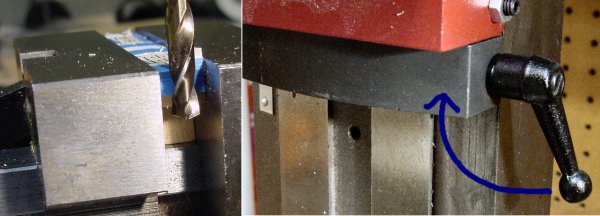
Scrap wood parallels are placed underneath the workpiece, the drill depth is checked, and then the milling/drilling stop is tightened.
The workpiece with taped template is placed on flat scrap wood (or metal parallels that are slide away later on) and tightened in the machining vise.
A 1/4-inch diameter drill is inserted into the drill chuck and the table is rolled to the side of the vise. The drill is lowered to the maximum desired depth and checked to ensure it won’t drill into the vise. At this point, the limit block (drill stop) is slide up against the headstock and the handle is tightened.

The screw hole positions are located by barely touching the paper template to determine if the bit is aligned with the printed crosshairs.
The two mounting screws are #4-40 flathead. The screw threads do not grip the brass face, but instead thread into the circuit board behind the face plate. Therefore, the hole is drilled out with a 1/8-inch diameter drill for clearance.
The cross hairs (plus sign) on the paper template visually guide the drill into position for the screw hole. By lightly tapping the spinning drill against the paper and scraping away some toner ink, you can tell if the drill needs to be nudged up, down, left, or right.
After drilling the 1/8-inch diameter hole, a countsink drill with an 82° angle is inserted into the drill chuck. This makes the angled hole for the flathead screw to sit flush in the brass face plate.
I keep a flathead screw nearby to test the hole depth. I drill a little, drop in the screw to test, remove the screw, drill a little, test, and so on. This is my least favorite and least accurate machining operation. I have yet to come up with a more reliable and repeatable method of drilling countersunk flathead holes to a perfect depth. Let me know if you’ve got a better way.
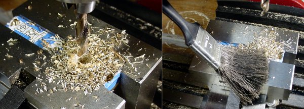
Drilling large thick holes produces a lot of chips and debris. This pile is too big! Use a cheap paintbrush to remove waste.
The button holes are 1/4 inch in diameter. The drill is positioned using the paper template, as before.
Good machine shop practices include pausing to remove waste material from the workpiece. Chips can clog cutters and can wear down cutting edges as the debris is repeatedly sliced and crushed into smaller pieces.
Turn off the mill or drill and then remove the chips with a brush. Or, better still, use a shop vacuum!
Never remove the chips with your fingers as they are sharp. You'll either cut yourself or end up with tiny metal splinters. Also, never use compressed air on a machine or on a workpiece on a machine. The air pressure can force chips into sliding parts or electronics in the machine.
A blue numeric LED display will be installed in the center of the brass face plate. A thick piece of clear polycarbonate plastic fits over the electronics for visual effect and to cover up the tiny gaps between the LED components and the brass display slot. The shape and dimensions of the brass slot are fairly critical, but the polycarbonate can be shaped to compensate.
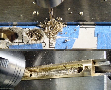
Drilling the corners of the square slot for the display with a small diameter drill. Milling out the rear of the face plate.
Square inside corners are difficult to make on a milling machine. Use a small diameter drill on the corners to at least get the radius down. However, be careful not to use such a tiny drill that it bends or walks. If that happens, the drill may cut outside of the display area and mar the face.
After all the drilling is complete, the face plate is turned over and the inside is milled out. As much as I dislike the thought of removing expensive solid brass, there needs to be room for the numeric LEDs, button flanges, and tactile buttons.
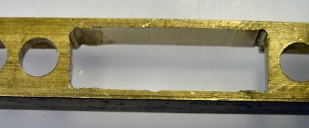
Brass face plate with unfinished slot.
After drilling and rough milling, the slot for the LED display is still pretty coarse. I was careful not to remove too much material. Now it is ready for one or two finishing passes to shave out the final dimensions.
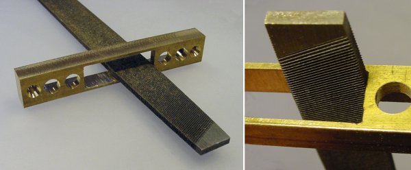
Burrs are removed and the corners are squared up using a file.
After the final milling, remove any inside burrs from the display slot with a metal file so that you don’t cut yourself when working on the slot corners. The final step is to square up the corners with a metal file. It takes a while. Be patient.
Solid brass buttons are placed over nondescript plastic tactile switches on the PCB. The finished metal buttons were so inviting to touch that the project had to automatically lockout the controls after several minutes to avoid inevitable presses from children and guests. (Pressing and holding the two end buttons at the same time unlocks the controls.)
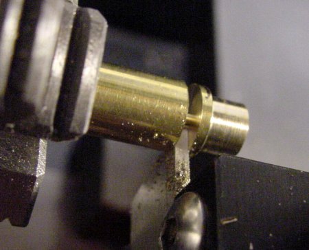
A 5/16-inch diameter stock brass rod is cut down from the supplied 6-foot length to a length that is more manageable. The rod is then inserted into a lathe.
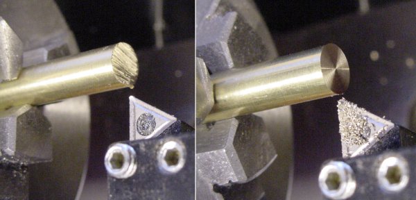
Cleaning up the end of a hacksaw-cut brass rod by facing it on a lathe.
The end of the brass rod is coarse from the hacksaw. Facing the end on the lathe makes it clean and square.

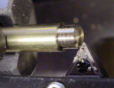
Turning down the diameter of a brass rod in a lathe.
The pushbutton holes in the brass face plate are 1/4-inch diameter. The rod stock is 5/16-inch in diameter. A portion of the rod needs to be turned down to slightly less than 1/4-inch to fit through the face hole without grabbing or binding when pushed. But, the button needs to retain a flange at the rear to keep the button from falling out.
Turning is often done with a different angle cutting tool than the angle of the tool that is used for facing. However, this perpendicular cutting angle is also acceptable for turning, since we want the flange to be squared off, rather than tapered.
Chamfering the button to eliminate sharp edges.
This cutting tool angle is satisfactory for removing the sharp edges on the business-end of the brass button. Depending on personal style, you can use a different angle.
After the desired amount of material has been removed, use a little sandpaper or a grinding attachment to round the end. If you prefer a more hand-finished look, you can sand and grind the button end after it has been removed from the lathe. This is more difficult, but it results in an uneven smoothness that provides a worn brass appearance.
Parting a one-piece brass button with a rear flange.
With the parting tool, make a parting cut that results in a slightly longer button than the desired final length.
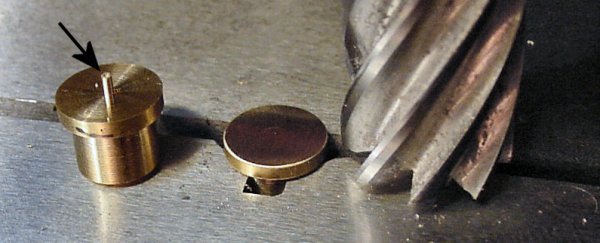
After parting, a tiny raised nub may be attached to the end of the button. To remove the nub and cut all the flanges to a consistent thickness, place the brass button into a v-groove of a milling machine vise with the flange resting on top. As long as you don’t change the height of the headstock or swap end mills, each button that is inserted and milled will have the same flange thickness.
Depending on the alloy used, brass is the easiest metal to machine. Although it has come up in price, a brass face plate and buttons can still be a reasonably small cost on a complex electronics project. Given how much time is spent making a custom device, it seems appropriate to finish it with a control head that ordinary people can appreciate.
Because of the weight, solid brass is probably not a good choice for a portable device or robot. Also, brass tarnishes. However, a lacquer coating can keep it looking shiny for a long time.