

I use the Sharp GP2D12 non-contact infrared sensor for determining the level of salt on the Water Softener Monitor project. To test the Sharp sensor and to determine the voltages at particular distances, I created a test apparatus out of a level and some machined plastic parts. This test setup is compatible with the whole family of Sharp distance sensors, which are capable of different measurement distances and different types of outputs.

A plastic level with a slide for measuring distances using an infrared electronic sensor.
The level was purchased from Ace Hardware (part #25793) for about $11. It is 4 feet in length (48 inches or 122 centimeters) and made from a stiff plastic.
Although the level includes three bubble barrel vials, they aren’t used for this project. Instead, this level was selected because it includes a ruler and is shaped such that it can be used as a monorail for a sliding target.

An optical target that slides and a sensor attached to the end of a level.
The distance sensor is attached to the end of the level where the ruler scale begins. A white sheet of ABS plastic is attached to a slide that can be positioned at various distances on the ruler. Other material can be easily substituted for the white ABS plastic, if a different optical target material or color is desired.
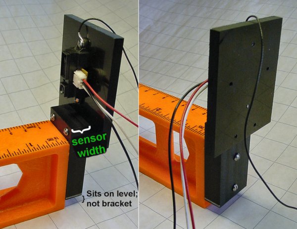
A Sharp infrared distance sensor attached to a bracket at the end of a level.
The thickness of the Sharp sensor is taken into account by the thickness of the mounting bracket. This way, the end of the level lines up with the lens on the sensor.
The bottom of the bracket does not go all the way to floor. This ensures that the apparatus rests on the bottom of the level, rather than potentially being tilted by the bottom of the bracket. This wasn’t a necessary feature for testing the Sharp sensors, but was added to the design in case a future usage required a level surface.

The slide for positioning the target on a level with a ruler.
Although the Sharp sensors claim to be unaffected by the angle of the object being sensed, the slide was made large enough to lie flat. The weight and length of the slide counterbalance any torque produced by the upright panel target. Additional weight can be added to the end of the slide if it turns out that the slide still doesn’t weigh enough.
The front of the slide has two screw holes for attaching the target material. Countersunk flat-head screws can be used if a sensor is being tested that can actually see the screw heads.
The slide is placed behind the target to avoid being detected by the sensor. Although, I suppose it could be placed in front of the target if an additional inch is needed at the end of the scale.
The front of the target is aligned with the scale lines on the ruler to establish the target distance.

Pads are attached to the bottom sides of the slide to prevent the slide from falling off the level.
The top of the level is shaped like a capital 'T'. Pads are attached to the bottom of the sides of the slide to form a t-slot. This holds the slide (and the attached optical target) onto the level. It’s a bit like a monorail train.
The pads screw onto the slide because the ends of the level are capped. If the slide and pads were machined as a solid chunk, there wouldn’t be any way to get it onto the level without altering one end of the level.
Although it is a little difficult to see in the photograph, there is a second set of screw holes above the pad screws on the slide. If the slide is too loose on the level, screws can be inserted to firm up the fit or even lock the slide in place. Unfortunately, the width of the cheap plastic level varies enough that I couldn’t find a firm fit in one location that wasn’t too loose or too tight at a different point on the level.
Before showing the oscilloscope traces and measurement results graph, let’s see how the test equipment parts were machined...