

(article continued from previous page)
The Flip-Flop Robot drives forward until it hits an obstacle, and then reverses until it hits another obstacle. This back-and-forth process continues indefinitely. By limiting the functionality to this very rudimentary behavior, it can be generated from an off-the-shelf chip instead of requiring a fancy microcontroller. Thus, this is a good robot project for beginners.
An even simpler circuit with the same functionality can be found at the Back-And-Forth Robot.

Robot direction 74HC74 schematic.
Avid fans of Robot Room will recognize the 7474 chip from the Laser Control project. This chip has two independent one-bit memory cells. You can read all of the operational details and see a movie in that article.
Briefly, the 7474 has a set (pin 10) and a clear (pin 13). The rear bumper switches are connected to the clear pin. When the rear bumper is pressed, the chip’s output (pin 9) is cleared (0V). This output connects to the motor driver chip and makes the robot drive forward. The function of the 7474 is to remember the output state even after the bumper is released.
The front bumper switches are connected to the set pin. When the front bumper is pressed, the chip’s output (pin 9) is set (5V), rather than clear (0V). This commands the motor driver chip to drive the motor backwards. The 7474 remembers this new output.
An oddity of the 7474 chip is that the set and clear pins are activated by a low (GND 0V) signal. Therefore, resistors R4 and R5 provide a high (5V) signal by default, so that the chip will not normally think that the set or clear pins are being activated. The bumper switches connect the appropriate pin to 0V when pressed, to activate the set or clear feature.
The power switch (SW1) connects the circuit to the battery when turned on. The diode (D1) prevents electricity from flowing in the wrong direction if the batteries are inserted backwards. Current is only allowed to flow in the direction of the arrow on the diode symbol. Backwards batteries would otherwise destroy the chips.
Capacitors C2 and C3 provide a smooth, local power source as the battery voltage goes up and down with power consumption. This helps prevent the chip from resetting or randomizing due to random electrical noise.
Bonus: The laser project only needs the bottom half of the 7474 flip-flop chip, and this project only needs the top half. You can combine the circuits to make a robot that starts and stops with a laser pointer, and that goes forward and reverse based on bumpers. You'll need to substitute the motor driver on this page for the FAN8200 motor driver chip. Simply connect the laser output (pin 6) of the 7474 to the enable pin (2) on the FAN8200, and the direction output (pin 9) of the 7474 to the input pin (6) on the FAN8200.
As discussed earlier, the bumper switches connect the corresponding input pins on the 7474 to GND (0V) when pressed.

Schematic of the front and rear bumper snap-action switches.
Snap-action switches have a nice feature where they can activate when the switch is pressed (normally-open pin) or when not pressed (normally-closed pin). In this case, we only want the 7474 chip to receive 0V when a switch is pressed, so the 0V (GND) wire is soldered to normally-open and the signal wire is soldered to common.
Notice that the front bumper switches are wired together (both connect to GND and both connect to the 7474 input pin 10). It doesn’t matter which switch is pressed -- or even if both are pressed at the same time. In any case, the input pin gets connected to ground. The same goes for the rear bumper switches.
The IXDN604 chip isn’t officially a motor driver chip. It’s actually a power MOSFET driver chip. However, it does an acceptable job supplying power to small motors.
Because this project only needs to drive a single motor, the 8-pin IXDN604 chip fits nicely in the small breadboard.

Simple single motor driver schematic with an IXDN404 (use the replacement IXDN604 now).
A similar setup is described on my H-bridge page. The IXDN604 is featured in Intermediate Robot Building. Both are good sources of information if you want more details. I usually place four diodes on the motor outputs, but that’s optional for a low-end project since MOSFETs have built-in body diodes.
Admittedly, a MOSFET driver chip is a borderline poor choice for the 4.5V-6V voltage level of this robot. MOSFETs perform better at higher voltages. This is not a criticism of the IXDN604 chip. The IXDN604 is wonderful -- I’m just using it in low-performance situation.
If you find that your motor isn’t turning, use fresh batteries to reach at least 6V. Alternatively, consider adding a higher voltage battery pack to supply power to this chip. (Continue to supply 4.5V-6V to the 74HC74 chip. Higher voltages will destroy it.)
Alternatively, use the FAN8200 chip instead. It runs well at lower voltages, but can’t operate above 7V.
As always, to help you wire this circuit in the real world, here are the direction controller and motor driver circuits on an actual breadboard.
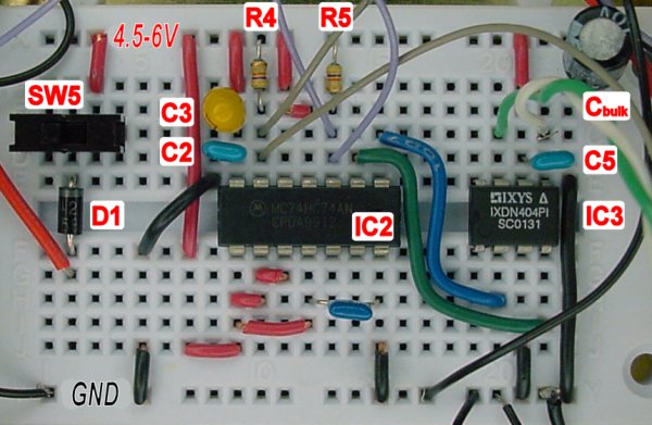
Flip-flop circuit on a solderless breadboard.
Despite well-thought out plans, robots have a way of not working when they should. Two major problems were encountered during this robot’s test drive:
Never feel bad if your robot has problems initially. Every robot I have ever built starts out with a serious malfunction. Tweaking the robot is part of the process and you should plan for it.
The first problem was the most time-consuming and frustrating. The robot drove forward, hit a bumper, started to drive backward, but suddenly reset to driving forward again even though the back bumper hadn’t been pressed. I was awake until 2AM trying the following:

Adding capacitors across terminals and metal tape around the motor to reduce electrical noise.
The GM7 is an inexpensive gearmotor -- which is great. However, it puts out a LOT of electrical noise. I added a couple of capacitors to the motor terminals and observed a moderate reduction in noise, but the noise was still significant. I even tried surrounding the motor with aluminum metal tape, without any apparent benefit.
I disconnected the motor from the circuit board and replaced it with a simple bicolor LED and a 330-ohm resistor. When the robot "drives" forward, the LED lights up red. When the robot "drives" backward, the LED lights up green. The circuit and bumpers worked perfectly fine with this setup. Therefore, the motor is the cause of the 74AC74 chip reset.
Now for the kicker: I connected the motor directly to an independent battery pack. That is, it was no longer connected to the rest of the circuit or robot power supply. Even so, simply applying power to the motor was enough to radiate electrical interference and reset the 74AC74 chip. Wow!
I was at my wit’s end. I had used up my bag of tricks to reduce electrical noise, but simply having the powered motor nearby was enough to prevent the robot from operating correctly. I was almost ready to cover the circuit board in a metal shell to act as a Faraday cage.
Before I did that, I decided to swap the 74AC74 chip for a 74HC74 chip. It provides the same functionality, but it uses more power and has weaker outputs. Surprisingly, the 74HC74 was much more noise resistant and didn’t randomly reset. Simply by using a 74HC74 instead of a 74AC74, I was able to restore the circuit to the basic parts described in the schematics at the top of this page.
This should serve as an important lesson that the “low-power” benefits of modern chips may make them more vulnerable to stray electrical fields.
With the circuit functioning properly, I was finally able to set the robot on the floor to enjoy its full glory. Sadly, though, it turned in a wide circle rather than going straight.
At first, I thought the problem was caused by the thin metal container bottom bending at the motor mount, causing the wheel to be tilted on the ground. The tilt would result in a conic wheel rotation. The tilt could be corrected at the motor mount with a shim, much as was done with the switch brackets.
Fortunately, it turns out that the robot’s weight was simply unbalanced. By shifting the battery pack away from the side with the motor, the robot’s motion straightened out.
Shifting the battery pack too far causes the robot to turn in a circle in the opposite direction. It is valuable to learn that an even distribution of weight is critical to a robot, particularly if the robot only has one wheel.
By the way, it is worth mentioning that both the solderless breadboard and the battery pack are attached to the candy-container body with Velcro hook-and-loop fastener strips. If I had chosen permanent double-sided sticky tape or screws, I would have been unable to balance the robot’s weight with slight shifts of the battery pack.
Don’t let these few negative issues give you the wrong impression about the final performance of the robot. Like all robots, adjustments make the difference between success and disappointment.
Positives:
You should consider making this robot, if only for the experience of using a flip-flop chip to remember a state. If you don’t have a suitable candy tin, you can base the entire body structure on a flat piece of balsa wood.
For an even easier circuit, check out the Back-And-Forth Robot.