

There are a number of methods for generating a clock signal for a microcontroller. Some microcontrollers include a built-in oscillator, however, pre-built canned oscillators and 32.768 kHz crystals are two of the most popular external methods.
In the past, I’d been using canned oscillators because they are so simple. Recently, I switched to 32.768 kHz crystals because of their flexibility. (An example robot that uses a crystal is the Bugdozer Sumo combat robot.) The following table relates to clock generation with a 68HC08 microcontroller.
 Oscillator |
 32.768 kHz Crystal |
|
| Approximate total cost each | $2.75 | $0.50 |
| Number of components | 2 (1 oscillator and 1 decoupling capacitor) | 9 (1 crystal, 5 capacitors, 3 resistors) |
| Professionally matched components | Yes | No |
| Electrical noise | More (MHz) | Less (kHz) |
| Software controlled speed | No | Yes |
| Programming requires component swap | Yes, depending on chosen speed | No |
| Cold start-up time | Less than 1 second | Up to 3 seconds |
| Reset start-up time | Instantaneous | Nearly instantaneous |
| Requires embedded software to engage | No | Yes, but included on this web page |
As you can see, a canned oscillator provides faster power-up times (in MHz speeds) and simpler designs. Whereas a 32.768 kHz crystal is cheaper and more flexible.

Schematic for 68HC08 and half-can oscillator
Very easy!
No special embedded software is needed. The processor bus is 1/4 oscillator speed by default.
Suppose you pick 32.768 MHz for maximum bus speed (just under 8.2 MHz). To program the FLASH from a personal computer, you'll need to physically swap in a slower oscillator, like 4.9152 MHz.
And what if you want the 6808 to run a little more slowly (say 2 MHz) for power savings but ramp up to maximum (say 8.2 MHz) during crunch time? It’s not going to happen. (However, you could use the HALT and STOP modes for power savings.)

Schematic for 68HC08 and 32.768 kHz crystal
A little more complicated, but nothing to be intimidated by.
All the component values were the suggested values provided in the MC68HC908GP32 Technical Data manual. This page originally suggested 24 pF for C1 and C2, and 330 kilohm for RS. But, revision 5 and later versions of the manual have the revised values as now shown. I find the circuit works either way.
Generally, the values of capacitors C1 and C2 should each be twice the capacitance of the crystal load (CL). You'll need to look up CL on the data sheet of the crystal you’re using. Then again, the 50 pF recommendation for C1 seems to contradict the notion of 2xCL.

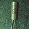
32.768 kHz crystal as implemented
For my example, the CL of X1 was 12.5 pF. I used 24 pF (for C1 and C2) instead of 25 pF, because that’s all I had lying around. No big deal. I tried the circuit with 20 pF and 39 pF and it still worked. I didn’t use a variable capacitor for C2 because I didn’t have one.
By default the 68HC08 bases its bus speed on the clock signal of the OSC1 pin. If the OSC1 pin is connected to an oscillating 32.768 kHz crystal, the bus speed is a whopping 8 kHz. Not megahertz; kilohertz.
Early on in the start-up code you'll want to tell the microcontroller to activate the PLL. This wonderful built-in module kicks up the speed up to 1000 times faster.
I created a table of popular speeds from the book. I then confirmed and supplemented that table using Mario Becroft’s wonderful online PLL calculator. I added SCI baud rate and A/D rate information to the table so those modules would be automatically adjusted to match the change in bus rate. (The original manufacturer had a wonderful seminar showing how to do all this stuff in code. My modules are based on their example.)
All you need to do is to call PLLSet with register HX set to the table entry of the speed you desire. Enjoy!
![]()
Click here to download the source file.
; Clock Generator Module / Phase-Locked Loop (PLL) routines.
; Copyright 2000-2004 by David Cook.
; www.robotroom.com

; 2000/09/04    DAC     Written.
; 2004/01/04    DAC     Added additional bus rate.
;                       Made sure no ADC rate exceeded 1.048 MHz, per REV 5 GP32 guide.
;                       Added some constants.
;                       Changed some formatting.


;********************************************
;*                                          *
;*                 Equates                  *
;*                                          *
;********************************************

; Remove the leading semicolon to uncomment the following equates if a gpregs.inc file
; isn’t included in your project or is missing these definitions.

;scbr               equ $0019
;
;pctl               equ $0036
;PLLIE              equ 7
;PLLON              equ 5
;BCS                equ 4
;
;pbwc               equ $0037
;AUTO               equ 7
;LOCK               equ 6
;
;pmsh               equ $0038
;pmsl               equ $0039
;pmrs               equ $003A
;pmds               equ $003B
;
;adclk              equ $003E
;
;ADIV2.             equ %10000000
;ADIV1.             equ %01000000
;ADIV0.             equ %00100000
;ADICLK.            equ %00010000


;********************************************
;*                                          *
;*                PLLSetup                  *
;*                                          *
;********************************************

; Example routine which sets up maximum bus speed. I call this early on startup.
; IN:  A, H, and X are ignored.
; OUT: A, H, and X are unchanged.

PLLSetup:
                   pshx
                   pshh

                   ldhx #BUS8200192
                   jsr  PLLset

                   pulh
                   pulx
                   rts


;********************************************
;*                                          *
;*                PLLSet                    *
;*                                          *
;********************************************

; PLLSet sets the PLL, ADC, and SCI (9600 baud) to the correct rates
; based on which address in the table below is stored in HX register.
; IN:  A is ignored. HX is bus rate table address.
; OUT: A, H, X, and CCR are unchanged.

PLLSet:
                   psha
                   pshx
                   pshh

                   tpa
                   psha
                   sei                      ; Don’t allow interrupts while
                                            ; we’re modifying the clock rate

                   bclr PLLIE,pctl          ; Disable PLL Lock interruptions
                                            ; (probably unnecessary).
                   bclr BCS,pctl            ; Select external reference as base clock
                                            ; because we’re turning off the PLL.
                   bclr PLLON,pctl          ; Turn off the PLL so we can configure it.
                   mov  x+,pctl             ; Program P (PRE1, PRE0) and E (VPR1, VPR0).
                   mov  x+,pmrs             ; Program L (VRS7-VRS0).
                   mov  x+,pmsh             ; Program N most-significant byte.
                   mov  x+,pmsl             ; Program N least-significant byte.
                   mov  #1,pmds             ; Program R to 1.
                   bset AUTO,pbwc           ; Enable automatic bandwidth control.
                   bset PLLON,pctl          ; Turn on PLL.

                   mov  x+,scbr             ; Program SCI Baud Rate register.
                                            ; Be sure to also mov
                                            ; {whatever|SCIBDSRC.},config2
                                            ; to select the internal bus as
                                            ; baud rate source
                                            ; wherever you initialize to
                                            ; write-once config2
                                            ; register in your code.

                   ; The Timebase Module (TBM) is connected to CGMXCLK (crystal frequency)
                   ; and as such is not altered by the configured bus speed.
                   ; So, no change is necessary to the TBM.
                   mov  x+,adclk            ; Program ADC clock register.
                                            ; Also note that the bus clock is also
                                            ; selected as the input clock source (ADICLK=1)
                                            ; by this mov instruction.

                   ; Comment out the next instruction if your application
                   ; doesn’t require clock stability before continuing.
                   brclr LOCK,pbwc,*        ; Wait for PLL to lock.

                   bset  BCS,pctl           ; Select PLL as base clock.

                   pula
                   tap                      ; Restore interrupts only if they were enabled.

                   pulh
                   pulx
                   pula
                   rts


;********************************************
;*                                          *
;*          PLLSet Bus Rate Table           *
;*                                          *
;********************************************

; Table of different bus rates when using a 32.768 kHZ crystal.
; ldhx #BUSxxxxxxx before calling PLLSet.
; To save FLASH space, feel free to comment out any rates you don’t use.

; The SCI, ADC, and TIM divide from the final BUS clock, not the original clock speed.
; (Actually the config register determines the SCI source of BUS or original.)
; The TBM divides from the original clock speed, not the BUS speed.

; Because this uses the PLL, the internal bus rate must always be used (ADICLK.).
ADCI_DIV__1        equ {ADICLK.}
ADCI_DIV__2        equ {ADIV0.|ADICLK.}
ADCI_DIV__4        equ {ADIV1.|ADICLK.}
ADCI_DIV__8        equ {ADIV1.|ADIV0.|ADICLK.}
ADCI_DIV_16        equ {ADIV2.|ADICLK.}

BUS1228800:                            ; 1.2288 MHz bus
                                       ; (Matches the 4.9152 MHz oscillator programming board.)
                   db $00              ; P  & E
                   db $80              ; L
                   dw $0096            ; N
                   db %00000001        ; Serial (SCI) = 9600 baud
                   db ADCI_DIV__2      ; ADC clock = 0.6144 MHz

BUS2007040:                            ; 2.00704 MHz bus
                   db $00              ; P  & E
                   db $D1              ; L
                   dw $00F5            ; N
                   db %00010000        ; Serial (SCI) = 10453 baud (Ick! Unusable)
                   db ADCI_DIV__2      ; ADC clock = 1.00352 MHz

BUS2457600:                            ; 2.4576 MHz bus
                   db $01              ; P  & E
                   db $80              ; L
                   dw $012C            ; N
                   db %00000010        ; Serial (SCI) = 9600 baud
                   db ADCI_DIV__4      ; ADC clock = 0.6144 MHz

BUS2506752:                            ; 2.506752 MHz bus
                   db $01              ; P  & E
                   db $83              ; L
                   dw $0132            ; N
                   db %00000010        ; Serial (SCI) = 9792 baud
                   db ADCI_DIV__4      ; ADC clock = 0.626688 MHz

BUS4005888:                            ; 4.005888 MHz bus
                   db $01              ; P  & E
                   db $D1              ; L
                   dw $01E9            ; N
                   db %00010001        ; Serial (SCI) = 10432 baud (ick! unusable!)
                   db ADCI_DIV__4      ; ADC clock = 1.001472 MHz

BUS4915200:                            ; 4.9152 MHz bus
                   db $02              ; P  & E
                   db $80              ; L
                   dw $0258            ; N
                   db %00000011        ; Serial (SCI) = 9600 baud
                   db ADCI_DIV__8      ; ADC clock = 0.6144 MHz

BUS5005312:                            ; 5.005312 MHz bus
                   db $02              ; P  & E
                   db $82              ; L
                   dw $0263            ; N
                   db %00000011        ; Serial (SCI) = 9776 baud
                   db ADCI_DIV__8      ; ADC clock = 0.625664 MHz

BUS7372800:                            ; 7.3728 MHz bus
                   db $02              ; P  & E
                   db $C0              ; L
                   dw $0384            ; N
                   db %00010010        ; Serial (SCI) = 9600 baud
                   db ADCI_DIV__8      ; ADC clock = 0.9216 MHz

BUS8003584:                            ; 8.003584 MHz bus
                   db $02              ; P  & E
                   db $D0              ; L
                   dw $03D1            ; N
                   db %00110000        ; Serial (SCI) = 9728 baud
                   db ADCI_DIV__8      ; ADC clock = 1.000448 MHz

BUS8200192:                            ; 8.200192 MHz bus
                   db $02              ; P  & E
                   db $D6              ; L
                   dw $03E9            ; N
                   db %00110000        ; Serial (SCI) = 9856 baud (borderline)
                                       ;                9938 is 3.53% too fast maximum.
                   db ADCI_DIV__8      ; ADC clock = 1.025024 MHz