

I’ve built quite a few robots over the years. Some of the robots have broken and a few were never quite tweaked to full operational capability. I decided to spend a weekend inspecting my robots; making any minor repairs or improvements as necessary.
Like all robot builders, when I look at a robot that I made several years ago (or sometimes several hours ago), I see a lot of mistakes and room for improvement. I could spend months rebuilding and retrofitting many of my earlier designs. It took every ounce of self-control to avoid the perfection trap. I vowed not to replace whole boards or redesign whole body parts. Instead, I focused on repairs (glue, solder, paint, filing, drilling) and part replacements (screws, capacitors, diodes, motors) only to the extent necessary to get the robot in good working condition again.
Sweet is a line-following robot featured at Robot Room.
At the rear of the robot, a pushbutton switch sticks out as the robot’s tailpipe. Pushing the tailpipe switch causes the robot to begin following the line course.
At the time Sweet was built, I used hot-melt glue to secure the switch in place. I’ve tried using hot-melt glue on several occasions and every time I’ve been disappointed with the results. Hot-melt glue is messy to apply. It also has a tendency to peel off of non-porous surfaces, such as plastics and metals -- which is exactly what happened in this case.

Hot-melt glue peeled off from the slippery-lined container of the Sweet robot.
It’s unfair to blame hot-melt glue in this particular case since Sweet is made from a candy container with a slick inside. I mean, the very purpose of the inside of this container is to prevent food from sticking to it. Nearly any type of adhesive, from tape to epoxy, will fail to adhere.
A mechanical fastener, such as a bolt, is a better choice to hold the switch in place.
I had to make a decision as to whether to remove the hot-melt glue from the switch and to glue the switch to a piece of machined plastic or metal that could be more easily attached with screws. (A good example of this technique appears on Figure 16-17 of Intermediate Robot Building.)
Well, I took the lazy route and decided to simply drill two holes through the metal container and the hot-melt glue. That was a mistake! If you’ve every drilled through plastic, you’ve probably accidentally melted plastic chips (debris) into the flutes (channels) of the drill by drilling too fast. (Drilling plastic at too fast of an RPM results in significant amounts of friction-induced heat, causing the plastic to melt rather than cut.)
Hot-melt glue is actually just thermoplastic engineered to melt at a lower temperature. So guess what happens when you try to drill through hot-melt glue? It melts.
I quickly gummed up one of my nicer drill bits -- even at what I thought was a reasonably slow speed. After picking out as much of the glue as possible from drill flutes, I was able to get the rest out by drilling through a block of scrap wood. Even so, I am suspicious that the drill retains some hot-melt glue at a microscopic level or in some unseen crevice.
Believe it or not, I chose a #43 drill for #4-40 screws. That means I originally intended to tap those holes in the hot-melt glue. I suspected all along that the soft glue wouldn’t hold screw threads, but I figured it was worth a try. But, after the experience with the drill, I wasn’t about to insert my fancy expensive tap into the hot-melt glue. Before giving up and ripping all of the hot-melt glue off of the switch, I decided to try inserting screws without tapping.

Screws grip quite effectively on unthreaded holes in hot melt glue, firmly holding the tailpipe switch in place on the Sweet line-following robot.
It worked! Okay, I admit it doesn’t look very professional.
The machine screws are held securely in the hot-melt glue. In fact, you can see in the picture above that the mere act of screwing in the screws seems to have melted or otherwise adhered hot-melt glue into the screw threads. No nuts are necessary. Actually, I can’t seem to get any nuts to go onto the screws because the hot-glue has gummed up the threads.
The switch is now firmly in place and Sweet is ready to roll again!
Hard2C is a mini-sumo robot. By painting it black and making it short, Hard2C is designed to be “hard to see” by its opponent. The robot is less than 4 cm tall at the front and 6 cm tall at the back.

Hard2C mini-sumo robot.
This was the first robot I ever machined parts for on my mill. I made a lot of beginner’s mistakes. For example, the top and bottom aluminum plates both have threaded screw holes for the same screws. Due to inevitable screw thread misalignment, the plates are not drawn together completely. (For more information on this subject, see pages 65 and 66 of Intermediate Robot Building.)

The error of threading both the top and bottom plates of the robot body causes a gap due to screw thread misalignment.
To correct this problem, I simply drilled out the #4-40 threads on the top plate with a 1/8-inch drill. Unfortunately, this process caused some damage to the paint.

Drilling out the threads in the Hard2C mini-sumo robot caused paint chip damage.
Sumo battles had already taken their toll on the paint, with chips, scratches, and scars. So, it was due for repainting anyway.
I prepared the surface with 220 grit sandpaper, followed by washing it off with a gentle detergent and water. After drying, I used ultra-flat black spray paint -- which exactly matches the paint used on the surface of the sumo ring.
Because Hard2C is so compact, there isn’t much room inside for all of the motors, batteries, sensors, and electronics. Every millimeter counts.
The motherboard PCB is shaped to share space with other parts. The PCB has a large notch cut out of it where the motor mounting block goes. I cut the PCB to this shape using my vertical milling machine. At the time, I didn’t realize I could have cut that part of the board parallel to the surface to create perfectly square interior corners.
Now that the board is populated with components and wires, it would be awkward to insert into a vise. Furthermore, it would be risky to subject the solder joints to the vibrations of milling given that I used a very thin sheet of copper board.
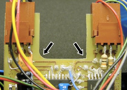
A square file shaved off the round edge (left) of the PCB, squaring it off (right). This provides more room in the tightly packed Hard2C mini sumo robot.
The solution was simply to use a metal file with a square profile. This removed the rounded PCB material and allowed the board to fit snugly against the motor mounting block. Even this little bit of extra space makes it easier to service and prevents wires and sensors from getting pinched.
Honestly, each of the aforementioned repairs were items encountered along the way to the important repair I was most interested in making.
During a sumo match, I noticed that at least one of Hard2C’s wheels weren’t spinning during a critical push. This was unexpected, as Hard2C has heavily-geared motors with more than enough torque to avoid a stall. My hypothesis was that somehow the drive train disconnects during periods of heavy load. This is a particularly fatal flaw in a pushing contest like robot sumo.
After disassembly, I found I could sometimes get the gear on the motor shaft to twist without the motor shaft turning. In other words, the gear slips.
Somehow, I needed to find a way to get the LEGO gear to firmly connect to the motor shaft. Yet, given the drivetrain design in Hard2C, the gear has to be removable for disassembly and there isn’t enough room to add a coupler. (For more information about the drive train in the Hard2C robot, see pages 406 to 408 in Intermediate Robot Building. For more information about connecting a LEGO gear or wheel to a non-LEGO gearmotor, see Chapter 20 of Robot Building For Beginners or Chapters 2 to 4 of Intermediate Robot Building.)
My friend Paul Jurczak brought in an interesting design to show off at a ChiBots meeting a few years ago. He threaded a setscrew through the hub of a wheel, and then covered the hole with the tire. That elegant design inspired me to thread a setscrew through the gear on Hard2C.


Left: A motor shaft inserted into heat-shrink tubing coated with epoxy to fill in the gaps of a standard LEGO gear. Set screws are added to secure the shaft to the gear while still permitting it to be removable. Right: Two set screws (one on each side) keep the shaft centered. The set screws are located in the thickest part of the plastic gear.
Pictured above is a standard LEGO gear. The 3 mm motor shaft of Hard2C’s Maxon motor fits loosely within the gear’s center hole (which is officially designed to accept a LEGO cross axle). This turned out to be fortunate. By placing a small section of heat-shrink tubing over the motor shaft, it fit more snuggly. Also, the tubing permitted me to fill in the rest of the gear’s center hole with epoxy without having the epoxy adhere to the motor shaft. (The epoxy sticks to gear and to the heat-shrink tubing, allowing the motor shaft to be withdrawn from the tubing when desired.)
At the time I built the robot, the motor shaft fit quite snuggly and the gear didn’t appear to slip. Either I didn’t notice the slip back then, or the epoxy or gear or tubing has stretched over time. In any case, the gear slips now and needs to be fixed.
I drilled a hole in the existing gear through the portion of the gear that has the thickest plastic. Hopefully, this location will avoid the gear splitting or the setscrew from slipping out due to too few threads.
Because of the narrow spacing of the gear teeth, there wasn’t enough room to use my standard #4-40 size setscrews. Instead, I stepped down to a smaller #2-56 setscrew. The narrow spacing of the gear teeth also made tapping threads more difficult, as the teeth caught on the sides of the tap before entering the hole. Fortunately, by selecting a taper tap and then a bottom tap, it was possible to successfully tap the hole without getting it crooked. (For more information about tap styles, see pages 45 and 46 in Intermediate Robot Building.) Another legitimate choice would be to choose even smaller screws.
Lastly, upon trying to install the gears, I discovered they would angle off axis with each turn of the setscrew. The pressure of the setscrew was either forcing the motor shaft into an unseen void in the epoxy or was warping the shape of gear. By adding a second setscrew on the opposite side of the gear, and by turning each setscrew a half a turn at a time, I was able to balance the forces and get the gear to stay firmly on the motor shaft without misalignment.
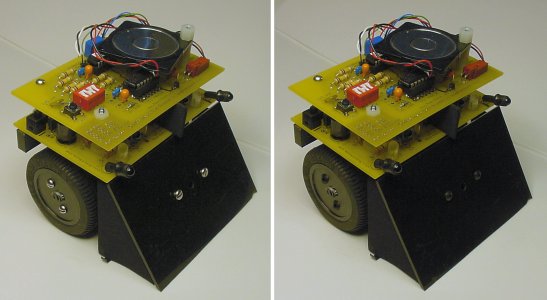
Roundabout is robot featured on Robot Room as well as in the book, Intermediate Robot Building.
When I entered Roundabout in the ChiBots Line-Following Contest I knew my configuration of the robot couldn’t win because I selected slow gearmotors for room exploring as opposed to speedy line-following. However, I had expected the robot to complete the course without any mistakes.
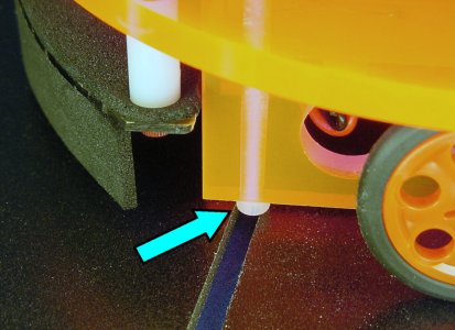
A standard socket cap screw head catches on the gap between the tiles in the ChiBots robot line-following course.
Unfortunately, I had installed standard socket cap screws for the robot to slide on. The raised screw head got caught once or twice in the gap between the tiles, causing the robot to become stuck until nudged by a human.

Left to right: nylon standard-head socket cap screw, stainless-steel round-head slotted machine screw, and stainless-steel button-head socket cap screw.
Pictured above are three types of screws that I’ve used on the underside of Roundabout. The standard socket screws (left) tripped up the robot. The round-head slotted screws (center) were the ones featured in the book. The robot would not have been as likely to have gotten stuck if I had kept the round-head screws installed. And yet, depending on the orientation of the slot when the slotted screw is fully inserted, it is possible for slotted screws to snag (especially on carpets).
The button-head socket screws (right) have a gradual slope, lower profile, and the hex driver hole is unlikely to get caught on anything. During my weekend upgrades, I selected this type of screw as a replacement.
During replacement, I noticed some gunk underneath one of the motor brackets. The exit hole (the side of the material where the drill finally breaks through, completing the hole) of a drilled hole is usually not as clean as the entrance hole (where the drill first makes contact with the workpiece).

Acrylic melted on the exit of a hole drilled in the Roundabout robot. This caused the motor bracket to fit poorly until the residue was scrapped off with a razor blade.
In this case, the motor bracket was resting on the debris, not flat against the piece it was supposed to be mated with. This weakens the joint and causes angling.
Roundabout’s motor bracket design is tolerant enough to endure imprecisions without significant consequence. However, a careful scraping with a razor blade removed the debris and corrected the situation. On metal, use sandpaper or a deburring tool to clean up an exit hole..
After fixing the exit hole problem and replacing the standard socket head screws with button head screws, I noticed that Roundabout tilted backward (by the weight of the battery) much more than before.

After installing button head screws, the reduced head height causes Roundabout to tilt backwards, exposing the line-following sensor circuit to outside light.
Because the button head screws have a much lower profile than the standard socket head screws, the back end of the robot wasn’t held up as far. By tilting back more, the gap in front actually provides more clearance for the fairly low-riding design. In other words, Roundabout should be able to clear slightly taller obstacles now.
The problem with having the robot tilt backwards is that ambient (room) lighting could now bounce off of the floor and into the line-following reflective floor sensors. The floor sensors provide their own light source via white LEDs. A flood of room lighting might cause the robot’s software to incorrectly judge a shiny black surface as being a white. (To learn more about the floor sensor circuit and light baffles, see pages 381 to 384 of Intermediate Robot Building.)
Fortunately, inserting longer spacers between Roundabout’s central platform and the floor sensor circuit was all that was required to lower the baffles far enough to screen out most ambient lighting. After making all of the corrections described, Roundabout successfully completed multiple laps on my test track without getting caught in the gaps or any other incident.
There is a mini-sumo configuration of Roundabout that uses the same circuit boards as regular Roundabout. This configuration won second place (in exciting “almost first place” multiple tie-breaker rounds) at this year’s contest. I decided to make a few improvements in hope that the robot will perform even better in the future.
I fixed a broken switch and further sealed the IR emitters against leaks. The wheel hubs were painted black as opposed to shiny, opponent-attention-grabbing bare aluminum. To further camouflage the robot, the shiny stainless-steel screws that are externally visible were swapped out for black-oxide coated screws.

Stainless-steel pan-head slotted machine screws (left) versus black-oxide coated button-head socket cap screws (right).
Over the years, I’ve tried painting screws black, drawing on them with permanent black marker, and even soaking them in black India ink. Shortly thereafter, the black coloring chips or rubs off, especially when tightening the screws in place.
I don’t know why I wasn’t aware of black-oxide screws before. Black-oxide not only looks good, but is primarily intended for corrosion protection. Black-oxide doesn’t rub off easily, since it is a chemical reaction that actually penetrates the metal.
Switching from bright, highly-reflective stainless steel screws (left) to dark black-oxide coated screws further camouflages the Roundabout mini-sumo robot.
Swapping out six screws (two on the scoop and two on each wheel) makes a noticeable (or unnoticeable) difference to the bottom half of the robot. Are these changes enough to tip the robot into victory? Stay tuned!
The last robot to undergo repairs is Chicago. This robot weighs about as much as a standard alkaline 9V battery and fits in the palm of your hand. And, yes, this robot follows lines using only solar power.

Chicago solar-powered miniature line-following robot with Miller solar engine, surface-mount Sandwich circuit, aluminum wheels, and sealed photocell sensors.
One of the things I like most about this robot is the way it looks. The wheels are particularly cool. The only downside of the aluminum wheels is their lack of traction. I should have made a groove on the outside of each wheel to hold a black rubber o-ring. (Instructions for making the wheels are on pages 58 to 65 of Intermediate Robot Building.)
Chicago’s electronics consist of two popular circuits merged together and shrunk down with surface-mount components. The first portion is the Andrew Miller 1381-based solar engine just like XS Boost uses. The second portion is the comparator-based line-following circuit that Sandwich uses.
The solar engine acts as the power switch, turning on the line-following circuit only when there is enough power to use the motors. Otherwise, the line-following circuit receives no power -- allowing the capacitors to charge up.
Two 1F (1,000,000 microfarad) 2.5 WV ultracapacitors are connected in series, providing 0.5F 5 WV of power storage. The ultracapacitors are very small. They fit underneath the robot.

A pair of 1F 2.5WV ultracapacitors and a DPDT dark-line / light-line selection switch on the underside of the Chicago solar-powered line-following miniature robot.
Also underneath the robot is a DPDT line-following switch. This allows the robot to follow either white or black lines, just like Sandwich. The only change from Sandwich’s line-following circuit is the use of a Texas Instruments TLV3702 comparator chip, since that operates at low voltages. (To learn more about Sandwich’s line-following circuit, see Robot Building For Beginners.)
Chicago’s motors were the smallest gearmotors I had ever seen at the time. They are only 12 mm in diameter and 22 mm in length. Since then, I have seen many equally small gearmotors of higher quality. And now, Solarbotics sells unbelievably tiny gearmotors with a diameter of only 6 mm.
But, like I said, these were the smallest gearmotors I’d seen at the time. And... I broke them.
The single piece motor mount was milled from nylon. (Aside, I should have chosen a lighter weight material.) The precision of the motor holes was good enough that the motors could be inserted and would stay put without requiring screws. However, “just in case”, the screws I selected to mount the PCB were chosen to be a tiny bit too long so as to act as setscrews for the motors. That is, the screw tips pressed against the motor case to hold it firmly.

PCB screw acting like a setscrew to keep the motor in place in the mounting block actually damaged the gearbox by pushing the thin shell into the gears.
What I didn’t realize was how thin the metal is on the motor gearbox. Instead of gently pressing against the gearbox, the screws actually bent or “dimpled” the gearbox casing. This alone wouldn’t have been so bad, except that the motor manufacturer placed several of the gears right up against the gearbox casing. I had the unfortunate luck of positioning the motor in the worst possible location, thus jamming the screw against the casing, which then jammed against the gears, thus seizing the motor.
Relieving the pressure by unscrewing the screws didn’t undo the indentation in the gearbox. I tried various methods of pulling the case outward, but ultimately I gave up and tried to carefully mill off the section of the case that had the bend in it.
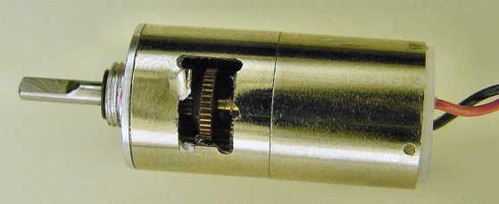
Exposed view shows how even a slight dimple on the thin motor gearbox casing caused it to make contact with the gearing, thus stalling the motor gearbox on this tiny gearhead motor.
As you can see, there is at least one large gear that almost touches the gearbox shell exactly where I chose to push a screw against. Milling off the casing resulted in metal chips flying into the gearbox. The gears are coated with a greasy lubricant, making chip removal almost impossible. As you might suspect, the tiny teeth of tiny gears do not joyfully accept metal chips.
This motor is dead.
I have since replaced the motor with one of the remaining stock. This time I chose shorter screws that don’t make contact with the motor. The friction of the precise fit of the motor in the nylon block is all that is necessary to keep the motor firmly in place.
Chicago performed acceptably at its robotic debut at ChiBots a couple of years ago. I was a bit disappointed in the overall speed, since my calculations lead to higher expectations. But, I never took the time to diagnose the difference until last weekend.

Chicago line-following solar robot undergoing diagnostic surgery via IC hooks.
The solar panel was partially detached and power fed in from a 5 V regulated power supply. The robot performed perfectly, powering the appropriate motor when presented with a piece of white paper acting as the line to follow.
To simulate the charging and discharging cycles that occur when solar powered, a 1 kilohm resistor was inserted between the power supply and the robot. Although linear current-limiting doesn’t exactly match the power-curve of a solar cell, it works well for the purposes of diagnosis. Furthermore, it’s a lot easier than sticking a bright lamp directly over the disassembled robot and waiting for the thing to charge.
What I discovered was that although the robot would charge up well, it would barely allow the motors and line-following circuit any time to discharge. This results in the robot receiving very brief pulses of power, over and over again quite often. It was supposed to take a while to charge and then get a while to operate during discharge.
The Miller Solar Engine provides the timer for discharge. The amount of discharge time is determined by a local power supply for the 1381, consisting of a small capacitor isolated by a diode. I figured that if the discharge time was too short that the capacitor value must be too small.
Desoldering tiny surface-mount capacitors is no fun. If you don’t have a hot air desoldering gun with the appropriate nozzle, the fastest method is usually to break the capacitor in half (nippy cutters or a milling machine) and desolder the two halves. This technique obviously results in the destruction of the capacitor (no big loss) but can also be stressful on the PCB. Since this circuit board was home etched on very thin copper, I wanted to be gentle with it.
Since I didn’t want to remove the existing capacitor, and since there wasn’t any room on the circuit traces to add another capacitor alongside, I decided to stack a capacitor on top of the existing one. Actually, at one point I stacked three together.

Stacked surface-mount capacitors increase capacitance on the timing portion of the Chicago solar-powered line-following robot.
The increased capacitance did improve performance slightly. However, the increased discharge time didn’t seem to follow the rate I expected. Something else other than the capacitor was the cause of the reduced discharge time.
I’m a big fan of Schottky diodes in H-bridges and in reversed-battery protection. Schottky diodes have a voltage drop of only a little over half the voltage of regular small signal diodes. That makes them very particularly valuable in the previously mentioned circuits, where a lower voltage trip point or lower voltage loss is important.
In exchange for this lower voltage drop, Schottky diodes tend to be electrically leaky in reverse. That is, even though ideal diodes as supposed to act like perfect one way valves, real diodes allow some amount of electricity to flow in the direction they are supposed to be blocking. Schottky diodes happen to allow a bit more reverse current than standard diodes. (For more information, see the reverse current graph Figure 8-12 on page 137 of Intermediate Robot Building.)
In the Miller engine, the diode’s job is to protect the energy in the local capacitor from being used for other purposes, such as for the motors or line-following circuit. By keeping the power local to the 1381, it stays on longer than usual, allowing the discharge time to be longer than usual. Upon inspection of Chicago’s circuit, I found that I used a Schottky diode instead of a 1N914 or other standard diode. Thus, through reverse current, the rest of the circuit was able to draw out some of the power that was supposed to be keeping the 1381 turned on. That’s why the discharge time was reduced.
By replacing the Schottky diode with a standard diode, the circuit performed as I originally expected, with longer discharge times. Actually, the discharge times were really long until I removed all of the spare capacitors I had stacked onto the circuit earlier.

Chicago miniature solar-powered robot following a line on a ChiBots robot club standard line-following tile.
I hope you enjoyed this visit to my weekend repair workshop. It’s amazing the difference that a couple of screws or circuit tweaks can make. Now, rather than a shelf full of sad robots giving me a guilt trip, they all seem happy once again.