

The previous page discussed the main PCB. This page goes into detail about the line-following PCB located beneath the front of the robot.
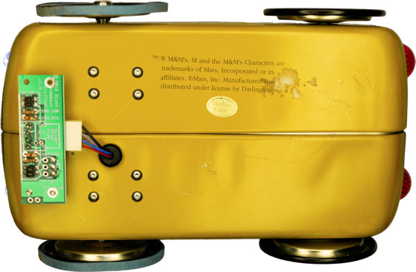
Underneath robot showing motor mounting screws and line-following board
The circuit itself is pretty basic. It consists of a pair of detectors that include a light source.
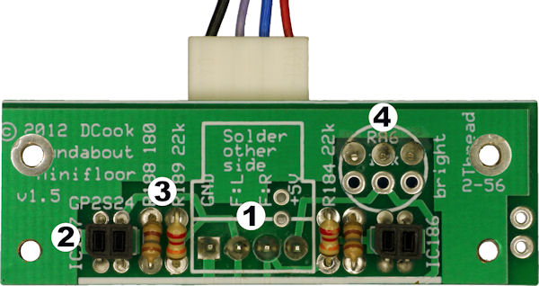
Line-following floorboard
The GP2S24 photosensors have an optimal detection distance of 0.7 mm. Looking at the graph in the datasheet, at least 50% reflectivity detection (compared to optimal performance) occurs when the sensor is positioned between 0.5 mm and 1.5 mm from the target. Yummy is closer to 1.5 mm, to balance detection capability with clearance height for unevenness in the floor surface.
The sensor gap didn’t leave enough height for the Molex connector to fit between the PCB and the robot’s body. So, I chose to trim off the locking ramp and polarizing ribs using a milling machine. This means I need to be careful when installing the connector to be sure it is the correct orientation. Also, if something snags the wires, the connector is more likely to come loose. Neither of these are serious concerns.
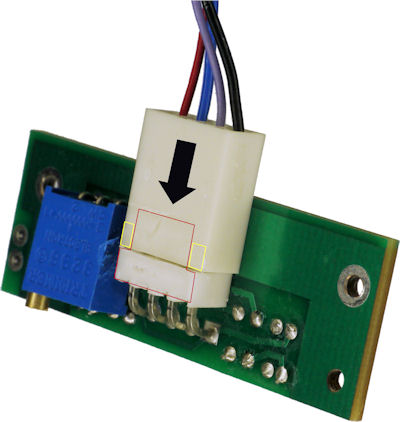
Molex connector machined flush
The candy tin separates vertically down the middle. PCBs cannot be fastened across the width of the robot, or else the tin cannot be opened. Therefore, the line-following board is attached to only one side.
PCB held onto one side with two screws
If I had been cleverer, I would have had the line-following board screw into the motor mount. But, since I designed this on-the-fly, there isn’t anything for the board to screw into on the other side of the sheet metal. So, the screw is inserted from above, passes through the sheet metal, through the nylon standoff, and screws into the PCB itself. The screw could have passed through the PCB as well, and been attached with nuts, however nuts have a tendency to vibrate off. This means I needed to tap the PCB.

Plated-through PCB hole threaded for 2-56 screw
The mounting holes in the PCB were sized to accept threads (0.067-inch hole for 2-56 screws). I’ve been threading holes in PCBs for many years. I assumed that the plating on the interior of the hole would be the material that would get threaded. However, now that I get a close look, I can see that the through-hole plating is lost in the process, and that the threads are made in the garolite substrate. I suspect that the threads in the substrate will have a much more limited life span of having the fastener installed and removed.
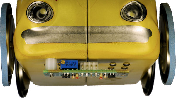
The wires from the connector pass through a hole into the candy tin container. The edges of the sheet metal are very sharp and may fray or cut the wires. Therefore, a rubber grommet is inserted into the hole to protect the wires.
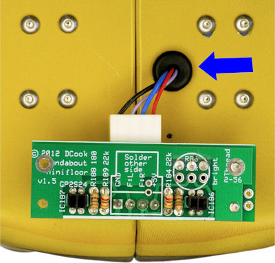
Line-following board motor mounting screws and rubber grommet
Sheet metal is notoriously difficult to machine. It is so thin that it flexes when you try to drill it. Also, the metal tends to warp and tear into the channel of a standard drill, causing the power tool to seize. A step drill is the appropriate tool for drilling sheet metal.
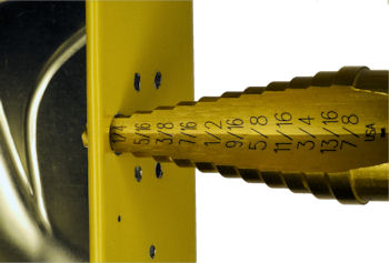
Step drill in sheet metal
Unfortunately, the position and width of the grommet prevents the two halves of the candy container from coming together completely. So, I had to cut a notch in the lip where the grommet is located.
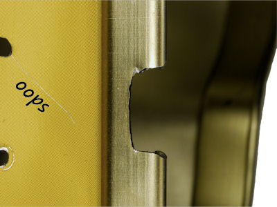
Ground notch in candy tin lip for wire hole.
Lest you believe my machining is perfect, note the paint scratch when my hand slipped during grinding or drilling. Next up, let’s take a look at the motor and motor-mounting block.