

Serial communication is a popular, easy, and successful method of sending and receiving data between two or more devices or computers. This technology is used in modems, network cards, USB accessories (universal serial bus), and RS-232 serial ports. It is so useful that serial modules are built into most microcontroller chips.
This article briefly describes and illustrates the most common serial communication employed by electronic hobbyists. The primary focus is on detecting transmission speed and how far off the bit rate can be before resulting in data corruption or errors.
“Serial” means sending one bit followed by another, rather than multiple bits over multiple wires simultaneously (parallel). “Asynchronous” means the sender transmits data using its own timing source, rather than sharing a timer or clock with the receiver. Asynchronous transmission provides greater autonomy and fewer wires, but the receiver must know the incoming data rate and each device must have a reasonably matching timer relative to each other.
There is a wide variety of asynchronous serial communication interfaces and protocols. So, I need to narrow the topic. First, we’re going to ignore the hardware interface by assuming that communication is occurring between two microcontrollers of the same voltage, or that a commercial RS-232 or USB chip is acting as the electrical adapter between a microcontroller and a computer. Second, we’re going to use the most common protocol of non-inverted, one start bit, eight data bits (a byte), 1 stop bit, and no parity.
In practice, a single output pin of the transmitting device is toggled high and low in a pattern that represents a piece of data. The receiver has a single input pin that is being read at a regular interval to store the incoming pattern.
For example, let’s say we want to transmit the letter 'U'. By agreed upon standards (ASCII, ANSI, Unicode), the letter 'U' has the numeric value 85. Inside the chip itself, the number 85 is stored in a byte made of digital transistor switches with the binary pattern 01010101. To transmit the letter 'U', the chip needs to output a pattern of 01010101, along with some overhead protocol bits.
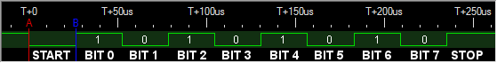
Trace of uppercase 'U' ASCII character (0b01010101 binary, 85 decimal, 0x55 hex)
When idle, the output pin is high (say 5 volts). You can see that the green line is 'up' at the very left of the above image. The output pin can stay high like that forever if there is no data to transmit.
When the output pin goes low (say 0 volts -- green line drops in the above image), the transmitter is signaling that a transmission is starting. The first bit is not data, but is an agreed upon consistent method of indicating a start.
Each bit must stay in that state for a specific amount of time depending on the transmission speed. In the above image, the bit length is indicated by the red 'A' and the blue 'B'. In this example, each bit takes about 26.0416 microseconds or 0.0000260416 seconds. A little math tells us that we can transmit 1/0.0000260416 = 38400 bits per second at this rate.
After the start bit, each bit of data is transmitted as low ('0') or high ('1') with rigorous equal timing. The data bit order is least significant bit (LSB) to most significant bit (MSB). To transmit the numeric value 01010101, the '1' bit must be transmitted first.
Finally, the transmission ends by raising the output pin to high again and holding it for the length of time of one bit. This is called the stop bit. It is not part of the data, but instead is the agreed upon method of indicating the end of that transmission. After this, the sender can go idle for as long as it pleases, or immediately follow that by the start bit of the next piece of data (repeating the process).
Now let’s send a carriage return (like pressing the enter key). That’s ASCII 13, which is 00001101 in binary. Remember that the lowest binary digit is transmitted first, so the bits appear in reverse order on the trace.
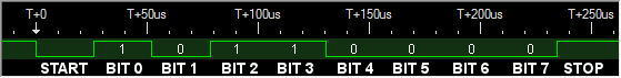
Trace of carriage return character (0b00001101 binary, 13 decimal, 0x0D hex)
The above shows that the receiver can’t expect to see high-low state changes for every bit. Depending on the data, the line may be high or low for longer than a single bit period. The receiver really does need to know the bit length (transmission rate) to accurately interpret the communication. To ensure success, the sender and receiver are programmed or configured in advance to a specific data rate.
What do the extreme cases look like, for example when the data consists of all zeros?
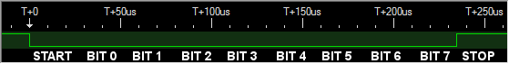
Trace off all low bits (0b00000000 binary, 0 decimal, 0x00 hex)
The above shows that the receiver can’t rely on the length of the start bit to autocalculate timing. The receiver would incorrectly assume that there was one very long start bit.
What about when the data consists of all ones?
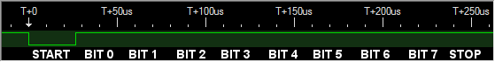
Trace of all high bits (0b11111111 binary, 255 decimal, 0xFF hex)
Nasty. It looks like the transmitter gave up or was busy doing something else. Nope, that’s a start bit (always low), followed by eight high bits, followed by a stop bit (always high).
Next, we'll look at the data rate and see how far off the timing can be before introducing errors.