

A while back, I created a robot that repeatedly drives straight until it touches an obstacle and then drives backwards until it touches another obstacle. The original Back And Forth robot is compact, driven by a single motor, and uses a solderless breadboard.

Although the robot isn’t particularly useful, the circuitry is inexpensive, simple, and off the shelf. That makes it a good design for a beginner.
For Back-And-Forth Mark II, I wanted to use the same basic circuit but:
That last point is a serious problem with the mechanical implementation (not electrical design) of the original robot. It is so lightweight and the tires are so slippery that the original robot doesn’t even have enough traction to activate the obstacle detection switches.
Let's see the robot in action, and contrast that to the original:
In comparison to the Lego wheels on the first model, the Mark II wheels are relatively tall (32 mm / 1.26 in) and the tires have a soft tread. They’re made by Pololu and are available from Solarbotics ($7 pair, part #RW32x07).


Back And Forth Mark II underneath with motors. Right: Pololu wheel 32x7 white 1088
The four wheels are all powered, so it has more than enough torque to toggle the snap switches. The motors are Sanyo NA4S gearmotors (Solarbotics $16 #GM14a) running around 70 RPM. There are a variety of Sanyo motors in that same form factor, so you can swap motors to drive faster or slower.

Sanyo NA3S style gearmotors
The motors have a D shape shaft (see Ⓐ in the image below). The Pololu wheel hubs were specifically designed to fit on the Sanyo motor shafts, so no set screw or special coupler is needed to attach them.
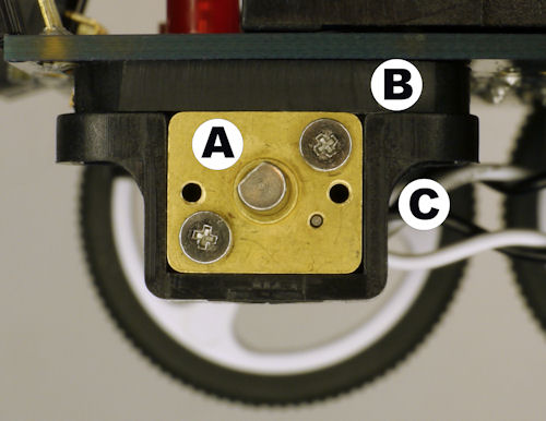
Sanyo motor mounted onto PCB
In the image above, you can also see a spacer Ⓑ (more on that in a minute) and a motor mount Ⓒ. The purpose of the motor mount is to firmly connect the motor to the robot. Just like the wheels, the mounts are made by Pololu (Solarbotics $5 pair, #51060) to specifically match the Sanyo motors. The combination of matching wheels, motors, and mounts eliminates a challenging problem most robot builders face.
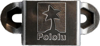
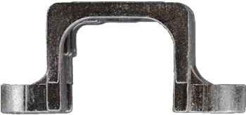
Pololu motor mount
The benefit of mounting motors directly to a printed circuit board is that “a body” is not required. The downside is that the pointy bits from soldered through-hole leads will prevent the motors from sitting flush unless you waste large blank areas on the board. Also, the metal housing of the motor could cause electrical shorts.
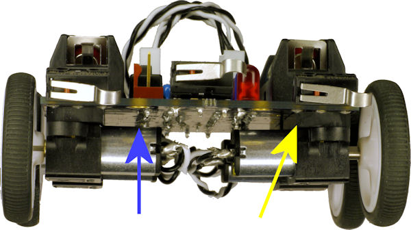
Back And Forth Mark II robot front view with pointy bits and spacer
The solution is to place a piece of material (called a “spacer”) between the mount and the PCB. This provides enough of a gap to prevent contact.
At first I thought that I could use a couple of plastic washers, but the Pololu motor mount lacks a top. That is, the mount relies on a surface above it to clamp the motor in place.
I wanted to avoid machining on this project, and I suppose I could have just made some spacers from cardboard. But I broke down and crafted some custom spacers from ABS plastic. They aren’t fancy. Each spacer is just a flat piece of 3 mm (1/8 inch) thick plastic with screw holes drilled into it. To prevent the corners from sticking out, the corners were crudely tapered with a Dremel grinding wheel until they matched the outer profile of the motor mounts.

ABS plastic spacer drilled and roughly ground into shape
The screw holes (Ⓐ in the image below) allow screws to pass through the motor mounts, through the spacers, and into threaded holes in the PCB. But be warned, PCB substrate is not reliable for threaded holes for production purposes, even if the holes were originally copper plated. However, the technique works fine for lightweight hobbyist designs, and saves the space and cost of nuts.

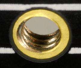
Custom spacer with screwholes and space for soldered pin. Right: Threaded PCB hole for motor mount screws
There is a larger hole (Ⓑ in the above image) to make room for a soldered pin of the battery holder. That takes us to the next page in this article, where the power supply and circuit board are discussed.