

A Solar Roller contest is where a robot races as quickly as possible to the finish line, with the robot powered only by a light source. The robot must not use batteries, rubber bands, or any other form of energy.
Solar Roller is considered a good contest for beginners, since the robot need only drive straight forward. A robot with only a single motor, no H-bridge, and no microcontroller can still be seriously competitive.
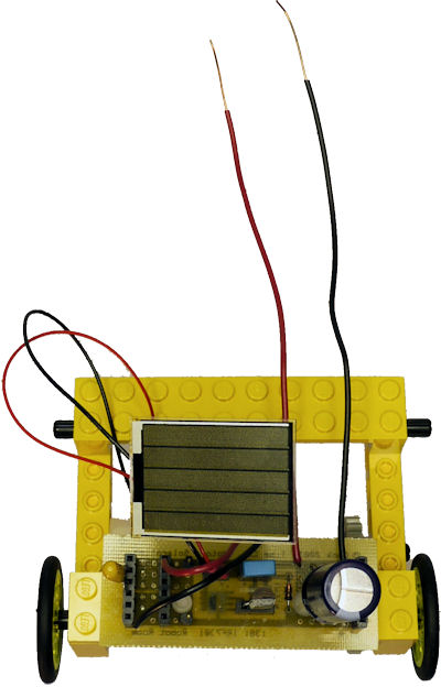
In this case, we see a simple robot:
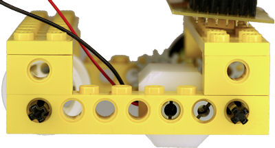
The long wires extending to the rear of the robot are the power rails (positive and negative). They touch a metal bar at the beginning of the course to ensure that the robot is fully discharged of energy before the start of the race, and to prevent the robot from charging up while it is waiting for the race to begin.
When it is time to race, the metal bar is dropped so that the robot’s power is no longer drained.
Even though Lightspeed could obviously be optimized to be smaller and lighter weight with lower-friction gears and axles, Lightspeed still won first place in solar racing at a ChiBots event. So, you don’t need a really fancy design to be successful.
Motors require quite a bit of electrical current initially, and then much less current to continue turning. Therefore, a small solar panel connected directly to a motor is unlikely to get the motor started.
The circuitry on Lightspeed is nothing more than a classic Miller engine such as used by XSBoost. Initially, the electricity from the solar panel is stored in the capacitor -- rather than going to the motor. When the capacitor voltage is high enough, the voltage trigger turns on the transistor and dumps the power to the motor to get it going. After that, the solar panel supplies power to the motor until the voltage drops enough that the transistor turns back off. Then the whole cycle repeats again.
Many Solar Roller robots operate in bursts -- with the motor powering the robot for a couple of inches and then stopping as it runs out of juice.
Because the initial expenditure of energy is so high, you want to keep the motor going for as long as possible to be efficient. But, you don’t want to spend the entire race sitting at the starting line charging up while your competitor is inching their way to the finish. So, you need to tweak the 'on' voltage and 'off' voltage to find the best balance for your robot’s combination of solar panel, motor, and weight.
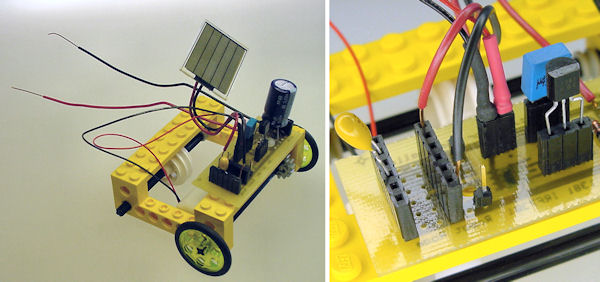
Lightspeed adjustable component sockets.
Rather than solder the capacitors and voltage trigger directly into the circuit, I installed them in sockets. This allowed me to swap in different values to find the best combination. This also allows me to reuse the PCB in other solar racers, where other component values might be more optimal.
Think of this as a hybrid between a solderless breadboard and a printed circuit board. The wiring is built onto the PCB, but the components are adjustable like on a solderless breadboard.
In fact, in case I want to experiment with different kinds of solar panels, the wires for the solar panel itself are not wired directly to the PCB. The panel power outputs are 22 gauge solid copper wire, which is compatible with the sockets. Furthermore, the thick wire holds its shape, so that solar panel can be angled toward the light source for optimal charging at the starting line.

Heat shrink tubing over headers to make a connector.
The motor has thin stranded wire that frays during attempted insertion into the socket, and also tends to slip out. So I soldered the wires to a jumper header, covered the joints in colored heat shrink tubing, and turned it into a connector.
Lightspeed uses mostly LEGO parts for the body and drivetrain. The rear is a centered, white, bare hub without a tire. This allows it to roll or slip with little resistance. (Every bit of friction or rubbing slows down the robot and consumes precious energy.)
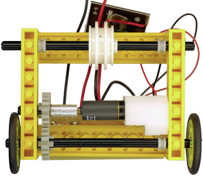
Single gearmotor rear wheel drive.
The front of the robot has two narrow wheels for less rolling resistance. The front axle is driven by a single motor. The single motor is preferable to one motor per wheel as differences in motors could cause the robot to veer into a wall and becomes stuck or slowed down by contact.
Besides tweaking electronic part values, a successful solar roller needs an efficient motor. Unlike cheap pager motors used in other solar robots, I purchased a very high-quality Maxon gearhead motor. Not only does this tiny 10 mm motor use rare-earth magnets and coreless windings, but also the gearhead converts some of the speed into torque, which helps get the robot moving for less energy. In fact, once started, Lightspeed can slowly drive the entire length of the course without stopping to recharge because the motor can continue to turn with only the power received by the solar panel.
Because the Maxon motor is not a LEGO part, it needed a custom piece to attach it to the robot’s LEGO body. This motor mount was machined out of scrap white nylon plastic. In hindsight, that’s an awfully big piece of heavy material for a racing robot.
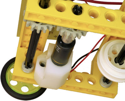
Gearmotor mount attaches with LEGO peg.
One side of the motor assembly is held in by a black cross axle (pictured above). Whereas a pair of LEGO pegs connect the other side of the motor mount to the LEGO frame (pictured below).
Two LEGO pegs prevent mount from pivoting in place.
Surprisingly, the gearmotor is friction-fit into the mount. That means there isn’t a screw or clamp to prevent it from rotating or falling out. Instead, the tight fit of the plastic holds the motor in place.
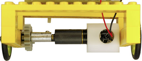
Gearmotor press fit into mount with hole for wires.
(Friction-fit is also called press-fit or interference-fit.)
The friction-fit was accomplished by using a 10 mm diameter drill for the 10 mm diameter motor. At first, you might think this wouldn’t be a very tight fit. But, the plastic compresses away during drilling and springs back slightly when the drill is removed. Therefore, the final hole is a hair less than 10 mm.
I intentionally avoided using a setscrew to hold the motor, after learning from the motor damage to the Chicago robots.
Is friction-fit reliable? Yes, in fact, all LEGO bricks are connected together via friction fit. On a robot this size, with its relatively low physical forces, a friction fit motor is fine. An even more unusual case is the friction-fit LEGO hub wheels on the Monkey Mint robot.
Solar Roller racing has declined a bit in popularity. Partially it is due to the need to create a race track, rather than just laying down tape to create a line-following course. But, even more so is that there is a simple winning strategy that causes the contest to devolve a bit in creativity.
Here’s how...
The year after Lightspeed won, another contestant brought forth the ultimate design. It was a small slot-car (low weight, powerful motor with slight gearing) that was fine-tuned to simply wait at the start of the course until it stored enough energy to zip to the finish in a single burst.
By doing so, the high energy cost of getting the motor moving was only paid once, rather than over and over as the robot inched towards the finish line. And, the solar panel could be titled directly at the light source at the starting line, rather than flat or at a compromised angle, since the panel wasn’t necessary to continue to charge or power the robot after it started moving.