

Last year, I read an article on BoingBoing.net about Archie McPhee (McPhee.com), which is an online store that sells novelty products. I purchased some Accoutrements Monkey Mints (item 11718, two for $4.95) for my sister and myself.
Although we were disappointed to discover that the mints are not made with real monkey, the amusing metal candy container is still worth the purchase price. In fact, the container is so much fun that it deserves to come to life as a robot.
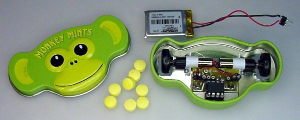
A robot made from a Monkey Mints candy container.
Featured below is a composite movie of the Monkey Mints robot following a white line on black tiles. About halfway through the video, some of the banana-flavored yellow candies are sprinkled onto the track. This creates an interesting pattern as the robot passes through the mints.
Please note: This article describes many of the parts and machining steps used to make this robot. However, it is not a step-by-step tutorial. If you or someone you know would like to build a line-following robot, see Robot Building for Beginners.
This is the smallest line-following robot that I’ve built so far. The robot is approximately 3 inches wide by 1.5 inches deep by 0.75 inches tall. It weighs only 32 grams, battery included.
A pair of incredibly small DC electric gearhead motors drive the robot. The motors are only 6 millimeters in diameter. That’s narrower than a pencil!
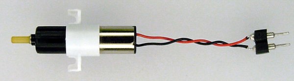
GH6123S 200 rpm 6 mm micro gearmotor.
These micro-planetary gear motors are available at Gizmoszone.com (GH6123S $18.90 each - 15% discount for 2). The white universal motor mount is purchased separately (GH612M $1.50). The mount and gearhead are made from glass-fiber reinforced engineering plastic.
Unlike plain pager motors, these motors include gearheads (the black portion in the above picture). A gearhead mechanically exchanges speed for an increase in pushing strength. If I had used an ordinary pager motor instead of a gearhead motor, this robot wouldn’t have moved.
The robot’s power source is a rechargeable Ultralife lithium-polymer cell. It supplies a voltage from 4.2V down to 3V, with a 180-mAh capacity. Because the robot’s electrical current usage is 140 mA, the battery should last approximately one hour.
This particular battery is a good choice because:
The battery came from Mouser Electronics, part #5169-UBC006 (aka UBC502030), $7.64. Unfortunately, according to a statement on Mouser’s website, it appears that Ultralife’s is no longer producing these types of batteries.
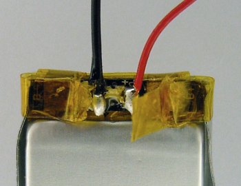
Ultralife lithium-polymer cell with replacement wires soldered on.
The factory-installed wires snapped off on one of my cells. The wires appear fatigued or fragile on the remaining cells that I hadn’t previously removed from their packaging.
Because of the high energy density of this type of battery chemistry, I don’t want to risk a fire or failure due to a wire coming off inside of a robot. Therefore, I desoldered the remains of the manufacturer’s wires and replaced them with my own.
If you choose to perform the same soldering surgery, you'll first need to cut away the yellow Kapton tape and then scrape off the plastic insulating coating. Be sure to use a non-conductive tool (such as a wooden toothpick) when scraping around battery terminals.
The various parts in the robot attach to the metal candy container with tiny stainless steel #0-80 screws and nuts, purchased from McMaster-Carr.
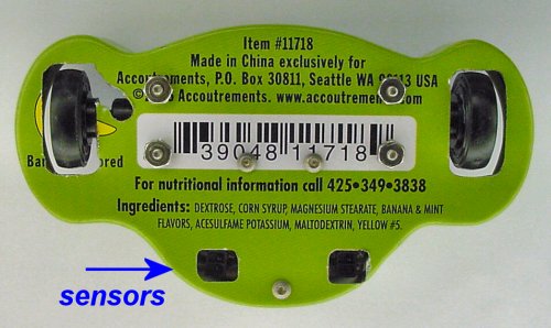
Underside of the shell of the Monkey Mints robot.
Three socket-head cap screws hold the circuit board in place. The fasteners come up from underneath and screw into 3/64-inch diameter holes etched into the printed circuit board (PCB). The PCB is professionally manufactured, which uses plated-through holes. Although plated holes are for electrical reasons, the metal plating also allows the holes to be tapped with threads for light-load purposes.
During trial laps, the front-most screw caught on the edges of the line-following course tiles. This stopped the robot from moving forward. To fix the problem, the front screw was simply removed. The two remaining screws are adequate to hold the circuit board.
The gearmotors are attached to the container with four screws and four hex nuts. I’d prefer not to have nuts outside underneath the robot, because nuts have a tendency to vibrate loose and fall off onto the ground. In fact, this actually happened during testing.
I don’t have many elegant options to work around this problem. The container’s sheet metal is too thin to tap for screw threads, and the gearmotor mounts seem designed to be clamped down from above with screw heads. Hex nuts don’t fit in the slots in the gearmotor mount.
Two appropriate solutions are:
The Monkey Mints robot reads the position of the white line using the same types of sensors as Jet, the ultra-fast robot. However, for the Monkey Mints robot, the sensors were selected for their small size, not their fast speed.
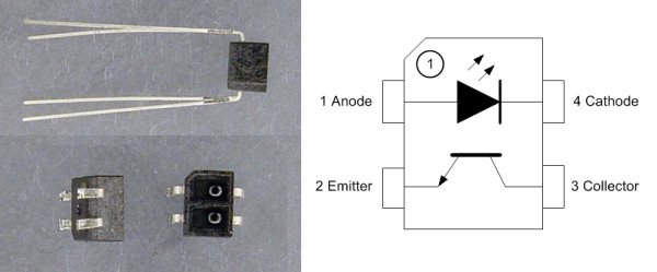
Trimming the long leads of the GP2S40J0000F.
The Sharp GP2S40 (DigiKey #425-2053-5 $1.60) has the longest wires I have ever seen for such a small component. This is a saber-toothed sensor! I had to clip off those bad boys for use in this robot.
Although there are many photoreflective sensors that have similar shapes and pinouts, these particular Sharp sensors have a long focal distance. That means they see well at a distance of 2 mm (100%) to 6.5 mm (50%) from the front of the sensor to the target. Most similar sensors peak around 0.6 mm and drop to below 50% at 1.5 mm.
This doesn’t mean that one sensor is better than another is; they are just different in lenses and/or emission angles. It is nice to know that you have choices based on how far away is most convenient for you to locate the sensors in your particular robot or electronic device. The sensors in Monkey Mints are positioned approximately 3 mm from the floor.
I rarely encounter errors in technical data sheets. However, I’ve run across what appears to be a copy-and-paste error in older datasheets for the pin numbering on the package drawings on these types of sensors. The Sharp GP2S40 datasheet does not contain this mistake, but I have learned to be wary. On such a small robot, I don’t have the luxury to cut and rewire copper traces to reroute electrical pathways for errant connections.
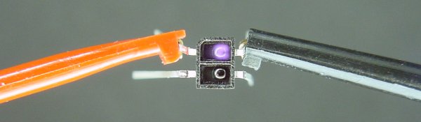
Testing an infrared photoreflective pair sensor.
If you haven’t worked with a particular model of photosensor before, they should be manually tested before designing them into a robot’s PCB. To begin testing, attach micro-hook test clips to the manufacturer’s specified chip leads.
The testing power source can be:
You can select a different power source than those listed above, but you must make sure that no more than 5V and 20 mA can be supplied. Otherwise, the sensor may be damaged while you experimentally hunt for the correct leads.
If the test clips are attached with the correct polarity (positive to the anode, ground to the cathode) to the infrared emitter, it will glow a faint purple when viewed with a digital camera. Because human beings cannot see infrared with their naked eyes, you won’t notice anything if you look at the photoemitter directly.
While you’re at it, you can attach 5V to a 24-kilohm resistor to the phototransistor’s collector, and connect the last remaining lead (the phototransistor’s emitter) to ground. The voltage at the collector will decrease when the sensor is exposed to light or a bright reflective surface. The voltage at the collector will increase then the sensor is shadowed or presented with a dark unreflective surface. The microcontroller brain in the robot reads the voltages of both phototransistors (on the left and right of the robot) to determine the location of the white line on the floor.
Continue to the next page to learn about the electronic parts inside of the robot.