

Model rocketry is a fun hobby for the entire family. Not only is it a wonderful excuse to go outside with the kids, but also it inspires young scientists and engineers.

Launching a model rocket.
I am a proud member of the National Association of Rocketry (NAR), which, along with the Tripoli Rocketry Association, has been educating the public and keeping the hobby going for over 50 years.
For the safety of yourself and others, always follow the manufacturer’s instructions and the Model Rocket Safety Code.
For less than $50, you can obtain an RTF (ready-to-fly) starter rocket kit that includes:
You need only supply batteries. The kits are available online and at some local hobby stores and hardware stores.
After success with the starter kit, you can take the next step that reflects your interests or experience:

Robot Room model rocket launch controller.
Photographed above, this is my custom launch controller. It uses an external 12 volt rechargeable battery for vigor, low-resistance current paths for maximum igniter energy delivery, and multiple safety features.
The purpose of a launch controller is to supply power to the igniter to fire the rocket motor. The tip of the igniter consists of a very thin wire (called the “bridge wire”) coated with a pyrogen/pyrotechnic (chemical compound that heats up). Think of it like an electrical fuse stuck into a match head, which is why igniters are sometimes called “electronic matches”.

Estes model rocket igniter before and after launching.
The thin wire heats up when sufficient electricity flows through it, which causes the pyrogen to combust (catch on fire), which initiates the burning of the solid rocket motor propellant. The thin wire is melted or vaporized in the process, which usually breaks the circuit, stopping the flow of electricity. (It is possible that the connecting clips or other portions of the wire will make contact with each other due to vibrations or rocket exhaust gas -- creating a short circuit.)
A launch controller should be designed to:
The Estes Electron Beam model rocket launch controller is included with all of the Estes starter kits. It is a marvel of cost-centric engineering, to keep the hobby entry price as low as possible.

Estes Electron Beam model rocket launcher controller.
Four AA batteries are installed into the controller itself to supply power. Approximately 17 feet of thin wire allows the user to operate the controller at least 15 feet from the launch pad. The end of the wire has alligator clips that connect to the rocket motor igniter.
The safety key is a metal peg with a tiny rubber o-ring. To prevent an accidental launch, the key must be inserted into a tiny hole and held down while pressing the launch button. Since the rubber on the key (and the metal strip inside the controller) pushes back, the key automatically pops out the moment the user releases pressure. This makes it unlikely that the rocket could be launched accidentally if the controller were dropped, set upside down, stepped on, or sat upon.
When the key is pressed in, but before the launch button is pressed, the “Ready” light bulb illuminates if there is a complete electrical path from the controller through the igniter. This won’t indicate if there is a short circuit (the alligator clips are touching each other), but it does indicate that there isn’t an open circuit (broken wires, disconnected battery, split igniter, or loose alligator clip).
Cutting open the Electron Beam controller reveals that the circuitry is very simple.

Inside the Estes Electron Beam.
The controller consists of a plastic molded case containing:
There are no chips, LEDs, capacitors, nor are there any resistors. In fact, none of the parts are polarity sensitive. This means you could install the batteries backwards and the circuit would still work just fine. Talk about an ideal minimalistic design!
It would be difficult to beat the Estes controller on price. However, you can make your own simple controller if you don’t have an Estes controller or if your Estes controller breaks. Here’s the schematic:

Schematic of a simple rocket launch controller.
In order for power to reach the igniter, there must be a complete electrical connection going from one end of the battery to one lead of the igniter, through the igniter’s pyrotechnic material, out the other lead of the igniter, and into the other end of the battery.
Consider what happens if the key is not in place. Electricity does not have a complete path even if the launch button is pressed. Therefore, ignition cannot occur by pressing the launch button by itself.
Likewise, ignition cannot occur by pressing the keyswitch by itself. Both switches must be engaged to ignite the rocket motor. Rule 3 of the Model Rocket Safety Code requires this type of launch system; it has a “safety interlock in series with the launch switch”.
Here is a launch controller that uses the same basic circuit.
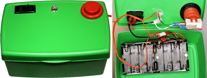
Homemade launch controller in plastic container.
A hefty power switch is placed in series with an arcade pushbutton. A large LED (with resistor hidden by tape) acts as the igniter continuity check. Eight AA cells are used to provide more power (approximately 12 V).
There are some potential weaknesses to this particular controller.
Model rocket ignition needs as little as 50 milliamps to as much as 23 amps, depending on the igniter (see Robert Briody’s great article on Electrical Current Requirements of Model Rocket Igniters). For the Estes igniter, the manufacturer says that the batteries need to put out at least 500 milliamps at 6 V. Alkaline, NiZn, and NiMH AA cells are all acceptable, with the latter cells capable of producing much greater currents.
Since electricity is going to flow through both switches, you need to make sure to use switches that are rated for such currents. Most switches are labeled with their maximum current in AC voltages without specifying the type of load (resistive, lamp, inductive, or motor). Unless you have access to the manufacturer’s datasheet, you aren’t going to know for sure.
A rule of thumb is to divide the AC voltage by 10 to determine the DC voltage for a similar current. So, a switch rated at 10 amps @ 120V AC will likely work at 10 amps @ 12V DC.
Why the disparity? Perhaps it is because AC voltage passes through 0 volts twice per cycle, which interrupts the arc that occurs when a switch is released.
If you fail to use properly rated switches, they could melt. Or, the contacts inside the switch could weld together such that the switch would not disconnect when you released it. If the igniter leads or alligator clips touch, the short circuit could destroy the batteries, melt the cables, and cause other damage. Or, a fresh igniter could immediately burn when a person was attaching it to the cable at the launch pad. This could be disastrous.
The homemade controller uses a rocker power switch instead of a spring-return or key switch. The rocker switch and arcade pushbutton could both accidentally engage if the box were dropped. More likely, the last person to launch a rocket will leave the rocker switch in the on position, due to their excitement and diverted attention when the rocket soars off the launch pad. When the controller is picked up again, the large launch button could be pressed. Or, if the controller is upside down or pressed up against something, the launch button could be engaged, causing harm during a short circuit or when attaching a new igniter.
A simple correction would be to purchase either a rocker switch or keyswitch with momentary on.
Given the same size cells as a 6 V battery, a 12 V battery delivers greater power to the igniter, resulting in fewer failed launches and possibly improved motor efficiency. However, it also means that more power is flowing through the continuity test bulb or LED. So, you must careful that the test current is below the manufacturer’s ignition limits (usually <50 mA).
An LED is superior to a light bulb for longevity and physical shock resistance. However, most LEDs are not as bright; which can be a problem in sunlight. Additionally, LEDs are polarity sensitive. That is, unlike a launcher with an incandescent light bulb, the launcher with an LED must have the batteries in the correct orientation for the continuity test to work.
Okay, so my simple rocket controller is inferior to the Estes in several important areas. It was a good try.
In the next couple of pages, we'll look at the major improvements in my next attempt at making a custom rocket launcher.