

I purchased a fighter pilot military toggle switch (the kind with a safety cover) to arm the igniter of a model rocket launch controller.

Side view of a covered toggle switch in the unarmed and ready-to-arm positions.
I am surprised how much larger the pilot toggle switch is compared to a miniature toggle switch, which is the size that I had become accustomed to using on robots or electronic projects. I’m not sure if anyone sells smaller switch covers for miniature toggle switches.
This particular switch is an illuminated toggle switch. There are major differences between a plain miniature toggle switch and the illuminated toggle switch due to the target voltage, internal wiring arrangement, and polarity of the LED in the switch’s tip.

Red LED inside illuminated toggle actuator.
The manufacturer apparently intends this toggle switch for automotive use, and thus selected an LED current-limiting resistor that provides maximum brightness at 12 V. Unfortunately, that means the LED is a lot less bright at 5 V.
If the manufacturer had allowed people to use an external resistor of their choosing, then some inexperienced purchasers would have connected the switch without a resistor -- resulting in blown LEDs. Those people probably would have returned the damaged switches to the manufacturer as “defective”. So, the manufacturer chose reliability and convenience for the target audience, in exchange for lower luminance when connected to lower voltages.
But the minimum resistance isn’t the biggest problem. The manufacturer wired the switch so that it connects the common wire to either 12 V (on) or nothing (off). That makes it difficult for a 5 V circuit to read the switch state. Instead, the manufacturer should have made it so that the common wire connected to either GND (on) or nothing (off).
I can’t swap the 12 V and GND wire, because the LED is polarity sensitive. It will only light up if I follow the wiring of the manufacturer.
I wanted to make the 12 V illuminated toggle switch compatible with a 5 V circuit. My first approach was to open the switch in hopes that I could rewire it.

Cracking open a toggle switch.
Two retaining tabs are bent out and then the entire side is lifted with a small flathead screwdriver.

Inside a toggle switch with LED. (The brass rocker has been pulled out to show the connections underneath.)
The ground wire goes up into the switch actuator, through the LED in the tip, through a resistor, to the common terminal. When the actuator is pushed to the on position, the rocker connects the common terminal to the 12 V terminal, completing the circuit.
In the simplest automotive application, you can see how this wiring arrangement makes sense:
Both the resistor and LED are buried in locations that make it almost impossible to desolder, replace, or rewire. Instead, I'll need to come up with an interface circuit to connect the 12 V switch to a 5 V circuit.
In the meantime, how am I going to get the toggle switch put back together?
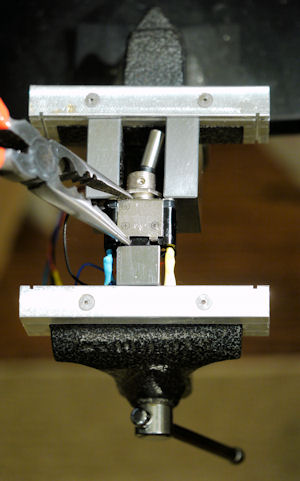
Putting a toggle switch back together using a vise and blocks.
To avoid damaging the actuator or solder tabs, I needed a way to force the metal case into position by compressing the top and bottom of the switch. The switch is placed in a vise with three square metal blocks directing pressure to the desired locations. I employed some “parallels” that are normally used in machining, but you can use stock raw material or anything square so long as one of them is narrow enough to fit between the switch leads.
A needle nose plier bends the switch case’s metal tabs back into locking positions.
The switch is not as good as it was before I opened it, but it works. The metal case bows out slightly and the metal tabs don’t grip as firmly as before. If you open your toggle switch, you might consider buying another one rather than trying to put it back together.
Because rewiring the switch isn’t practical, on the next page you'll see how to interface a 12 V switch to a 5 V circuit.