


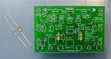
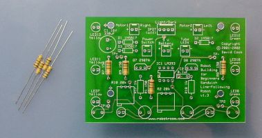
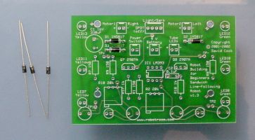
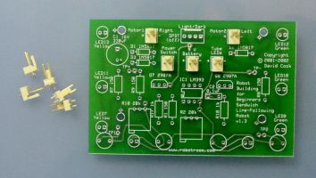
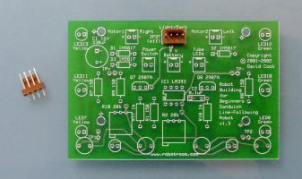
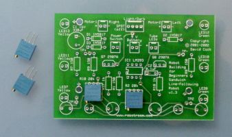
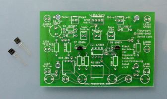
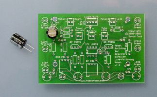
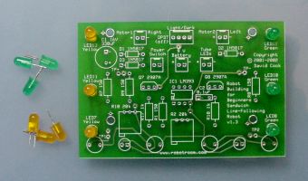
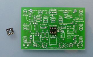
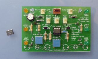
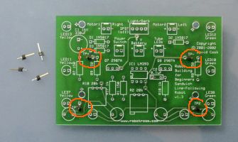
Sandwich’s printed circuit board. Left: unstuffed. Right: finished.
This contains component placement instructions for the printed circuit board (PCB) for Sandwich, the line-following robot. If you received a printed copy, you can check RobotRoom.com/SandwichPCB.html for the most recent instructions.
This information is applicable for boards matching my template, whether you purchased a ready-made board or etched your own. In any case, you must have the book Robot Building for Beginners for complete instructions on the entire robot. The page numbers listed in this document refer to pages in the book.
The Sandwich PCB has now reached version 3.0. Thank you to all of the robot builders that have purchased Sandwich boards over the last couple of years!
The newer boards are identical to the previous boards in regards to size, component placement, mounting screw holes, and so on. Therefore, don’t worry if your board looks slightly different than some of the pictures (for example, your board may have extra holes here and there) -- these instructions remain valid for all Sandwich PCBs.
For the benefit of you and the environment, the v3.0 boards are made with silver/tin instead of lead. To avoid tarnish, leave the PCB in the resealable bag until you’re ready to solder. Or, remove any tarnish with a pencil eraser (see RobotRoom.com/PCBTarnishEraser.html).
A complete parts list spreadsheet (beyond just the motherboard) and other cool information can be found online. See the link towards the top of page 425 of the book. But here are the parts needed to populate just the motherboard:
Two 1-kilohm resistors (R17 and R18). The board is designed to fit 1/2-watt resistors, but the smaller 1/4-watt and 1/8-watt resistors work fine as well. Either end of the resistor can be inserted into either hole.
Four 150-ohm resistors (R1, R7, R8, and R9). Either end of the resistor can be inserted into either hole.
Very Important Critical-To-Success: Instead of a 150-ohm resistor for R1, use a 10,000-ohm or 100,000-ohm resistor for R1 if the resistance of your unique photoresistors causes the voltage at TP1 or TP2 to exceed 6 V when the robot is placed on a dark surface. (If LEDs don’t light up as expected during testing when you move the sensors over a line, this is probably the problem).
Three 1N5817 or 1N5818 Schottky diodes (D1, D2, and D3).
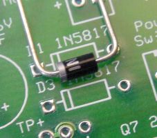
You must insert all diodes such that the end with the band (stripe) matches the correct hole, as illustrated on the board’s silkscreen layer. The board will not work if you insert a diode in reverse orientation.
D3 is the diode referred to on page 496. This prevents the board from being damaged if the battery is connected backwards and the power switch is turned on.
Optional: If you don’t want the slight reduction in speed caused as a side effect, you can simply insert a bare wire to connect the holes instead of a diode. However, you can’t leave D3 blank, as the board won’t function.
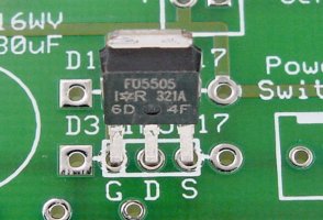
Optional: As an alternative to D3 or a blank wire, the v2.0 boards (and newer) include three holes to optionally accept a p-channel power MOSFET (such as the IRFU5505). This provides reverse battery protection with improved performance over a Schottky diode. For detailed information on this trick, see pages 103-106 of Intermediate Robot Building.
Recommendation: Because a protected circuit and line-following accuracy is preferred to speed, I do NOT recommend you install a blank wire or a MOSFET. Instead, I highly recommend you install a Schottky diode in D3.
Optional: Five 2-pin Molex male headers. If you don’t want to use Molex connectors, you can save money by soldering the motor, 9 V battery snap, power switch, and m&m’s tube LEDs wires directly to the board.
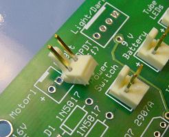
You should insert all of the headers such that the plastic friction lock (the tall plastic part that looks like the back of a chair) faces the outside of the board. The friction lock helps prevent strain from pulling apart the connection. The friction lock also makes sure you don’t insert the female housing in the wrong orientation.
Optional: One 4-pin Molex male header for an offboard DPDT line-following switch. Make sure the friction lock faces the rear of the board, just like the 2-pin headers. This connector is optional if you choose to install the tiny line-following switch instead (see below) or if you solder the switch wires directly to the board.
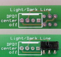
I prefer the offboard light/dark line-following toggle switch in the rear of the Ziploc container as shown on Figures 6-8 and 6-9 on pages 82 and 83. However, it can be a bit of a pain to wire.
So, starting with the the v2.0 boards, there is a set of 6 optional holes that you can either:
In any case, either use the standard 4 holes for the line-following switch connector or the optional 6 holes, but don’t hook switches to both.
Two 20-kilohm trimmer potentiometers (R2 and R10). Multiturn trimpots are desirable as they don’t slip out of adjustment as much, and they can be adjusted parallel to the board (page 86) using a screwdriver. The board is designed to fit Bourns 3296 style trimpots.
Two 2907A PNP bipolar transistors (Q7 and Q8). You'll need to bend the leads out slightly to fit them into the holes.
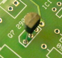
Since the leads are spread out from the case, don’t try to insert the transistor case all the way -- it doesn’t need to be pressed up against the board.
Make sure the flat side (usually containing the part-number text) of the transistor faces forward, which matches the shape of the illustration on the silkscreen of the board. If you insert the transistor backwards, that half of the board won’t work.
Just for the fun of it, I wanted to see if Sandwich would be faster or more energy efficient with field-effect transistors instead of bipolar transistors. So, the v1.4 boards (and newer) include three holes below Q7 and Q8 marked GDS. It stands for Gate, Drain, and Source -- which are the pins on FET transistors.
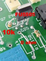
If you’re inclined, you can leave off the 2907A transistors in Q7 and Q8. Instead, connect the first hole to the second hole (from left to right) in Q7 and Q8 with a 10 kilohm resistor. This causes the gate pin to receive + voltage by default, which is necessary because many comparators only pull down to GND (-).
Solder a P-channel field-effect transistor (such as an International Rectifier HEXFET IRFU5505 with the leads tapered a little to fit into the pre-v2.0 holes) in the GDS holes. Because base current limiting is no longer necessary, you can solder a wire across R17 and R18 instead of a 1 kilohm resistor. It doesn’t matter much either way.
All of this being said, I found no measurable improvements in performance or battery life. So, I’d stick with the standard 2N2907A bipolar transistors if I were you.
Optional: One 330-microfarad (or greater) 16 WV (or greater) capacitor (C1).

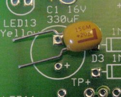
Large value capacitors are usually either aluminum electrolytic or tantalum. If you choose aluminum electrolytic, insert the lead with the negative band into the hole marked '-'. If you choose tantalum, insert the lead with the positive band into the hole marked '+'. Nice of them to stay consistent in their markings, huh?
If you insert the capacitor in the reverse orientation, the capacitor will be damaged and the board may fail to operate.
Optional: One 0.1-microfarad (or thereabouts) capacitor (C2). Small value decoupling capacitors are usually ceramic, and can be inserted with the leads in either orientation. However, a '-' is printed near one of the holes on the board in case you choose a polarized component.
Three yellow (LED7, LED11, LED13) and three green (LED8, LED10, and LED12) T13/4 LEDs. Choose other colors if you prefer.
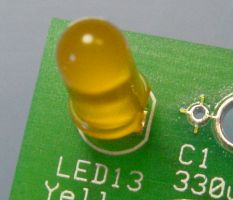
Make sure the flat notch of the LED matches the illustration on the silkscreen of the board. If you insert any of the LEDs backwards, that string of LEDs won’t light up.
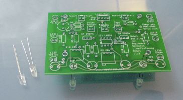
Two white (LED9 and LED10) LEDs. Note that the part-number labels appear on the opposite side of the board from the majority of the other parts. This is to indicate to you that the LEDs go on the opposite side of the board since they’ll be facing (and lighting) the floor.
The shape of the LED must match the illustration on the silkscreen layer (the flat notch on LED must match flat notch on the picture) or neither white LED will light.
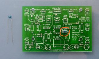
Four cadmium-sulfide photoresistors (R3, R4, R5, and R6). Note that the part-number labels appear on the opposite side of the board from the majority of the other parts. This is to indicate to you that the photoresistors go on the opposite side of the board since they’ll be facing (and examining) the floor. The leads of the photoresistors can be inserted in either orientation.
Prior to insertion, the backs of the photoresistors should be coated with black paint. Alternatively, encapsulated or hermetic (sealed in a metal can with transparent window) can be used instead of photoresistors with painted backs. The v2.0 board (and later) includes a copper layer at the front of the board to help block out ambient lighting.
Don’t solder the photoresistors directly up against the board. See page 436 for height instructions.
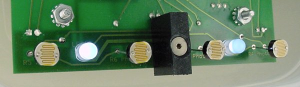
Optional: Starting on the v2.0 board, there’s a screw hole in the center of the front that can be tapped for a #4-40 screw or left plain for a #2-56 screw with a nut. You can use this hole for anything you want (or ignore it), but the hole was designed so that you can attach an opaque barrier to act as a light baffle (preventing light from the left side from affecting the right side, and vice versa).
Because the white LEDs are spaced far enough from each other, the baffle isn’t blocking much light. Test results do not indicate any value in using a baffle on this robot.
One 8-pin DIP IC socket (to hold IC1).
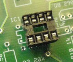
Make sure the rounded notch in the IC socket matches the illustration on the silkscreen layer. Although the socket will work in either orientation, it might fool you into inserting the chip in the wrong orientation.
One LM393 dual comparator (IC1). Make sure the rounded notch in the IC matches the notch in the socket or the illustration on the board’s silkscreen layer. Otherwise, the board will fail to operate and the chip could be damaged.
To prevent damage from heat during soldering, the chip should only be inserted in the socket after all the soldering on the board is complete.
There are four “official” test points on the board, TP+, TP-, TP1, and TP2. You can attach a piece of wire (pointing out straight or in a loop) or a 1-pin standalone header to each hole to allow hook clips to attach for testing. Or, you can leave the test point holes alone and ignore them.
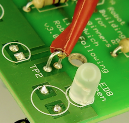
Personally, I recommend you use a loop of bare wire for the test points. This makes it easy to secure an IC hook test lead probe when calibrating the sensors.
There are four large screw holes on the board. These are for attaching the finished board to the robot’s body (see page 469) with #4-40 or #2-56 screws. On ready-made boards, the screw holes are not threaded -- the screws should simply pass through. If you’re etching your own board, you can choose to drill a smaller hole and tap it, if you desire.
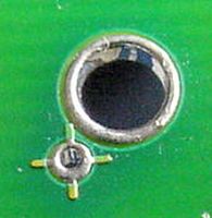
Ignore if you purchased a ready-made PCB. On home-etched boards, adjacent to the screw holes are crosshairs (plus signs). If you’re etching your own board, the crosshairs can be used to align both sheets of the PCB transfer film before ironing them on to each side of the board.
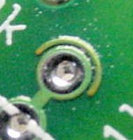
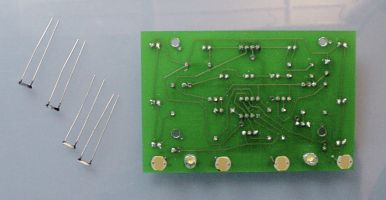
Left: half circle marks a via. Right: Bare wire soldered on both sides of the board to complete a via
Ignore if you purchased a ready-made PCB. Throughout the home-etched board are a number of holes with a half circle above them. These indicate locations where the front side of the board needs to be electrically connected to the back side of the board. If you’re etching your own board, you'll need to insert a bare wire (no plastic insulation) into the hole and solder the wire on both the front and back sides.
If you’ve got a ready-made board, ignore the half-circle holes; the board manufacturer has plated through the holes, making the connection and saving you time.
You can obtain the professionally-manufactured ready-made board from Solarbotics (part #SandPCB). They also have a kit available, part #K SAND.
>> Somewhere on your web site you mention that the board is exposed on the Solarbotics kit. Does that mean their board is too big to fit into the sandwich shell?
No. I just meant that their version of Sandwich doesn’t have the plastic container as a body.
Solarbotics uses the standard-size, high-quality board with solder masks and silk-screening. Their board is the latest version of the exact board shown on this page.
Solarbotics figured out that they could optimize the kit (and bring down the price) by attaching parts directly to an open/exposed board rather than suspending the parts in an upside-down plastic container. Here are the parts they were able to eliminate in their configuration of Sandwich:
If you want, you can purchase the above parts (see the book for part numbers or download the spreadsheet from the resource web page listed on Page 425) to supplement the Solarbotics kit to build Sandwich to look like the book. That is, you can build their version of Sandwich and have it work just fine. Or, you can buy their kit and add the additional parts and have it work just fine.
Solarbotics made an improvement that is not related to the container. They have wheels that press onto the motor shafts. As such, there is no need to hand-make your own LEGO-wheel-to-standard-motor coupler (Chapter 20) if you buy the Solarbotics kit or purchase their motors and wheels separately. The Solarbotics motors and wheels are much less expensive than the motors from Jameco Electronics.
>> Are there any downsides to building your robot from the whole Solarbotics kit?
No, not that I know of. In fact, you can save money and get a head start even if you plan to reconfigure the Solarbotics kit to the book’s version of Sandwich.