

If you grow sunflowers, you’ll be amazed at how they slowly rotate their head to constantly face the sun. By morning they’ve turned around to do it again.
I wanted to recreate the heliotropic behavior of a sunflower by using a single motor, many sensors, and a microcontroller. But, not every project turns out well. In fact, I abandoned the project due to a design error with the sensors, and because it looks junky. The incomplete tracker has sat atop of display case, gathering dust for eight years.
Sun Tracker unfinished
As I was cleaning up my files, I ran across the photographs I took back then of the construction process. I thought some people might be interested, so I took some additional photos and wrote up this mind dump of what I could remember about it.
There are sixteen analog cadmium sulfide (CdS) photosensors spaced evenly around the perimeter of the Sun Tracker to detect the brightest source of light. This allows the Sun Tracker to notice and turn towards the morning sun, even after facing the opposite direction from the night before. At night and during overcast days, the Sun Tracker won’t bother powering the motor, as it can determine that doing so would be a waste of power. Most importantly, no calibration is required regardless of where the device is placed in the yard, since it automatically seeks the sun.
The sensors are soldered to unique pairs of wires on the outside of the device.

Wires through acrylic guides with photosensor soldered on
The wires are threaded through colorful plastic insulators to keep the wires from touching each other. I chose translucent yellow for artistic reasons, and I chose acrylic because it has excellent resistance to weathering. The plastic comes in a sheet that is cut on a table saw.

Cutting acrylic sheet on miniature table saw
To get the correct dimension, I lined up the saw guide using the PCB to which the wires will connect.

Cutting strips the width of the PCB
A milling machine is used as a drill press to make all of the holes. (Expert machinists may notice that I didn’t make proper use of the table, as the final two rows are missing their holes. More on that in a minute.)

Drilling wire holes in acrylic strip
I chose a 0.036 inch carbide bit for sharpness, but that was a mistake. Carbide is brittle and my machine is too loose. After breaking a bit, I switched to high speed steel (HSS), which is more forgiving.

Carbide bit breaks so use high speed steel
Unfortunately, the flexibility of the HSS drill bit combined with my “get it done quickly” attitude resulting in sloppy hole placement.

Quickly drilled acrylic is not good but not awful
If you want to do it correctly:
After drilling, the acrylic strip is cut down into smaller pieces using a hacksaw. I chose a hacksaw because trying to cut such small pieces on a table saw gave me visions of missing fingertips.

Cutting acrylic guides with hacksaw
The result is functional, but looks like it was made with hand tools by a seventh grader. The holes are uneven, the corners are chipped, and the row of holes is not centered between the edges.
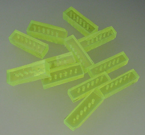
Fluorescent yellow acrylic wire guides
Uninsulated wires of 20 AWG (0.032 inch diameter) are threaded through the acrylic spacers. I wish I had chosen thicker wire for a little more mechanical stability. To somewhat make the correct shape, the wires were bent around a suitable object, such as a wet/dry shop vacuum filter.
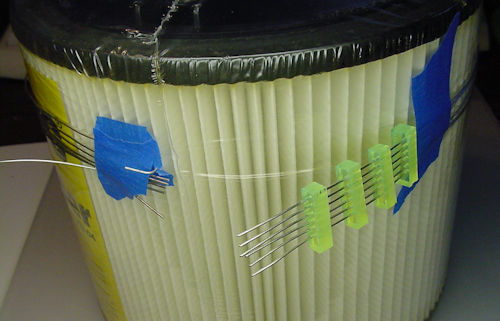
Wrapping around wet vac filter for shape
Each end of the wires is connected to a small PCBs that connects to the motherboard.

Dual bus connections to motherboard
The wire circle is then snipped into two separate electrical busses, consisting of half a circle each. On the other end, the wires connect to a dead-end perf board and are screwed together for mechanical and shape reasons. A nylon washer keeps the soldered tips of the wires from each half from touching together.

Bus loop physically connected by screw with non conductive spacer
Now the sensors can be soldered onto the wires, in a carefully planned arrangement (more on that later).

Soldering photocells in vise
Below is what the loop looks like during soldering. Notice the PCBs at the top and the bottom. This really consists of two half circles connected together.
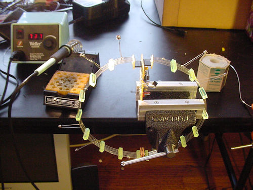
Halfway through soldering
Rising up next, let’s spot how the microcontroller reads all of those sensors -- or doesn’t.