

The entrance to our local Target store has bargain bins. I discovered a plastic Desktop Traffic Light toy (item #234010093 UPC 0 84431 27558 9) that seemed like it would be fun to open up and modify (hack). It cost $2.50, batteries not included.

8.5-inch tall decorative stop light.
When three AAA batteries are installed in the base, the traffic light repeatedly flashes a sequence of red, amber, and green. This is annoying for two reasons:
Of course, if this device were perfect, there would be less of an excuse for me to inspect the insides and make changes. As it turns out, this traffic light is much more hackable than most novelties.

Phillips-head screws in the base and the main signal case.
The first pleasant surprise is that the plastic lids are held on with screws rather than glue. Both the battery base and the traffic-signal main enclosure can be easily opened and resealed with a Phillips screwdriver.
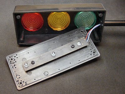
Traffic light project box showing color filters and a circuit board.
The main enclosure is particularly roomy. In fact, it could be easily reused as an electronics project box.
There are three ultra-bright wide-angle LEDs (red, amber, and true green) that could be desoldered, if desired. These are decent LEDs! (Aside: Did you know that modern traffic lights mix a little blue with the green to help color-blind people?)
There are also three 1.5-inch colored-filter lenses that might be useful in a robotic light sensor, but they will require some effort to remove.

Two sizes of pan-head, sheet-metal screws.
The main circuit board is held onto the back cover with two screws. Oddly, these screws are a slightly different size than those used on the box lid. Why not just make all the screws the same to reduce the number of different parts?
All of the screws are classic sheet-metal style (sharp points and threads) made out of ordinary steel. If you are going to open the lids repeatedly, you should consider re-tapping the holes for machine screws and switching to stainless-steel screws.

Milling-machine tool marks inside the case lid.
Despite years of practice, I still consider myself an amateur machinist. However, based on the circular swirls on the inside lid of the traffic light, I’d say I’m much better than whoever worked on their injected-molded dies. Maybe he/she just had broken or dull tools? I suppose there was no practical reason to polish the inside surface as they did the outside.

Underside of stop-light circuit board shows black epoxy covering the chip.
Unscrewing the single-sided circuit board reveals that the machinist is also in charge of soldering wires, apparently. Notice that the wires are soldered on top of the hole, rather than being inserted. The blue “button” wire is the worst; the white “ground” wire is fine.
The chip (likely an ultra-low-end 8-bit microcontroller) is covered by a solid black blob of resin. The blob is dark and opaque to keep out light -- which alters the operation of semiconductors. It is solid to seal the chip against moisture.
Many inexpensive items, such as toys, feature these packageless chips (dies) that are covered in epoxy resin. It is called “chip on board” or COB construction.
The leads from the LEDs on the front of the board stick through to the back. Each anode (positive lead) connects directly to the positive rail (+4.5V) from the battery pack. Each cathode (negative lead) connects to a separate pin on the chip, allowing each LED to be controlled independently by making a pin positive (to turn off) or ground (to turn on).
I expected to find current-limiting resistors to protect each LED, but none appears. The most likely explanation is that the chip is programmed to apply “full power” for a very brief amount of time. Done correctly, this generates a brilliant flash without overheating the LED and without the added expense of resistors. Most chips are unable to provide much drive current, so current is already somewhat limited.
Nevertheless, lacking current-limiting resistors means this chip is unable to keep the LED lit steadily. It can only flash the LED. It might be possible to simulate a steady light by flashing the LED faster than the human eye can perceive -- a process called pulse-width modulation or PWM.
Before hacking this board, let’s look inside the base of the traffic light.