(article continued from previous page)
The wall plate for the water softener monitor displays a bar graph of the salt levels in the brine tank. If the wall plate looks like an ordinary light switch plate with an extra hole, then I’ve done a good job making it fit in.
In actuality, the wall plate for the salt level monitor began as an uncut blank wall plate (#7526K89 McMaster-Carr). The square hole for the LED bar graph and the round hole for the light sensor were cut out on a milling machine.
The first step in the machining process is to draw the plate design on a computer. I use Microsoft Visio.

Computer aided drawing (CAD) of custom wall plate.
The dimensions for the blank plate and the LED bar graph come from the manufacturer’s datasheets. The diameter of the light sensor photocell was measured using digital calipers.
After entering the shapes and arranging them as desired, I placed 1/16 inch diameter holes at the corners of the bar graph rectangle. Then, I set the origin (0,0 point) to the upper-left corner of the wall plate drawing.
Clicking on each point of interest (rectangle corner holes, wall plate screw holes, and the photosensor hole) displays the coordinates in millimeters in Visio. The coordinates were then manually noted in black text in the drawing itself so that they would appear in the print out.
For example, the leftmost screw hole has the coordinates 17.86,37.31 written above it. That means the center of the screw hole is 17.86 mm to the left of the left side of the wall plate, and 37.31 mm down from the top of the wall plate.
A plastic wall plate is too thin and flexible for a vise to hold it securely during machining. There needs to be an indirect way of holding it.

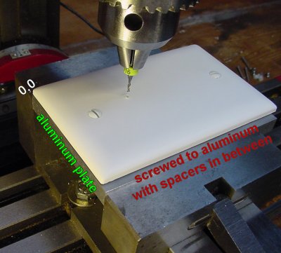
Blank wall plate mounted on aluminum stock in a milling machine vise.
A flat stock plate of aluminum is placed in the milling machine vise, with the upper left corner of the vise being located as 0,0 (see here for instructions on finding the vise origin using an edge detector). Using the digital read-out display on the milling machine, screw holes are drilled at 17.86,37.31 and 101.20,37.31 per the paper template. The holes are then tapped for #6-32 screws, which appears to be the standard screw size for household electrical plates in the United States.
The blank wall plate is then screwed onto the aluminum stock, with spacers (waste stock or washers) in between to hold up the wall plate during machining. If the spacers weren’t added, the plate would warp when tightened down and the drilling/milling operations would cut into the aluminum plate. This would make machining more difficult and would make the aluminum plate less reusable for future projects.

Milling the outline of the bar graph display on the blank wall plate. Notice that the end mill does not cut into the aluminum.
After placing a 1/16 inch end mill into the milling machine, follow the coordinates on the computer drawing from corner to corner for the bar graph rectangle. This results in the outline of the bar graph rectangle being cut out on the wall plate. Pretty slick, eh?
If you don’t have a digital read out, you can tape the paper drawing to the blank wall plate and follow it visually. If you don’t have a milling machine, you might even be able to score and cut out the outline with an X-Acto precision knife or razor blade.

Drilling the light sensor hole in the custom wall plate by starting with a smaller drill and working up to the final size.
The hole for the photosensor is nearly 1/2 inch. To avoid breaking the plastic or jamming the drill, start with a smaller pilot hole and work up to the final hole gradually with several drill sizes in between.
In the above photograph, did you notice how rough the edges of the cuts are? Although the blank wall plate was listed as “nylon” by the retailer, it appears to be polycarbonate on the manufacturer’s spec sheet. Regardless, some plastics simply don’t machine cleanly.
The rough edge is actually stretched plastic on the entrance and exit of the cut. Remove the excess plastic with a sharp metal edge, such as square stock or a razor blade. Be careful with a razor blade -- it tends to gouge plastic if used too aggressively.

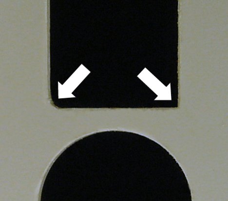
The left corner is rounded from the end mill. The right corner was then squared with a file.
As you can see, the edges cleaned up nicely, with only some slight residue remaining. However, the corners of the LED bar graph rectangle are rounded due to the shape of the end mill. The LED simply won’t fit.
A square-shaped file or triangular-shaped file can square up the corners. Depending on the type of plastic, it may take a little patience.
It is time to mount the custom wall plate...