

(article continued from previous page)
Earlier in the article, I explain that the line-maze solving robot counts wheel rotations to map the robot’s location in the maze. The location can be used to save a tile-based representation of the maze in an EEPROM. Subsequent runs can be completed faster since the robot doesn’t need to take any wrong turns.
If the wheel encoders are sufficiently reliable and have high-enough resolution, it is theoretically possible to rerun a maze without using the line sensors at all. That is, the robot would merely advance a certain distance (measured by the wheel encoders) and turn at the previously determined points. This is called “dead-reckoning”. In practice, a dead-reckoning robot will drift and likely end up off-target without some real-world feedback along the way.
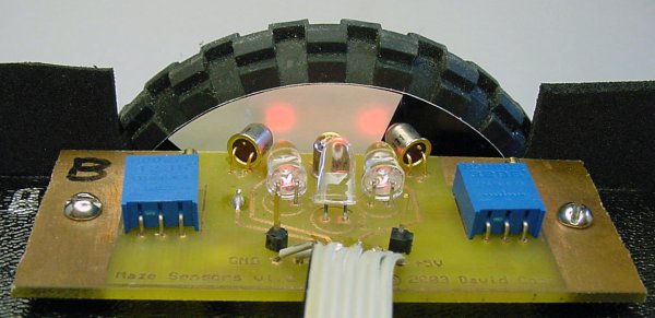
Encoder sensor board.
The encoder sensor boards are on the left and the right underside of the robot. Surprise, surprise! The encoder boards are actually just floor sensor boards with two of the phototransistors aimed at the wheel instead of the floor. The middle phototransistor still aims down at the floor to detect lines at a maze intersection.
Reusing circuit boards for multiple purposes makes it faster to complete a robot. I didn’t need to create another type of PCB, and the same software processes sensors from both the floor and the encoders.
In the above picture, notice the bright red dots on the paper encoder target on the inside of the wheel. Those red dots are created by the clear plastic ultrabright red LEDs. You can see the metal encased phototransistors are aimed directly at the red dots. If I had used infrared emitters instead of visible red, it would have been more difficult to aim the emitters and sensors this well.
By the way, don’t try the red-LED trick with other colors unless you have matching photosensors. Red is near enough to infrared in the spectrum that these infrared phototransistors can pick up the red light. Blue and green would have not registered at all.
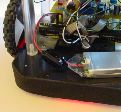
Red light from the emitters of the floor and encoder sensors seeps out from under the robot’s baffle.
There is a black baffle that runs along the perimeter of the robot to prevent ambient light from confusing the sensors (see pages 380-383 in Intermediate Robot Building). An attractive side effect of using red LEDs is that the robot’s light shines through on the sides of the robot’s base. You can also see this red light on the robot’s wheels.
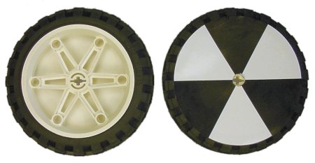
Lego wheels with a homemade paper encoder disc.
Using a computer-drawing program, I designed a disc that matches the diameter of a large Lego wheel. The disc has dark sections and light sections. The disc was then printed out on heavyweight photo paper and taped to the wheel.
Unfortunately, one of the downsides to photo paper is that it is fairly glossy. This means that even the dark areas reflect a significant amount of light at certain angles. While I appreciated the flatness and rigidity of the thick paper, I recommend that you stay away from glossy stock.
The encoder sensors detect light and dark segments passing in front of the photosensors, just like is done for detecting maze lines passing underneath on the floor. Because there are two sensors aimed at the encoder disc, it is possible to subtract the value of one sensor from the other sensor to perform autocontrast detection. That is, if the difference of one sensor from another is great enough, then the lighter sensor must be seeing a white segment and the darker sensor must be seeing a black segment.
By counting the transitions from light-to-dark and dark-to-light, the robot can determine how far the wheel has turned. In addition, by keeping track of the order in which the sensors go to dark or to light, the robot can determine the direction of motion and can avoid miscounting if a wheel jitters back and forth at a transition point.
The two-input technique for determining direction, speed, and distance of rotation is called “quadrature encoding”. I have written an article that describes algorithms for quadrature encoding in painstaking detail, including using analog polling, digital polling, or interrupt-triggered processing.
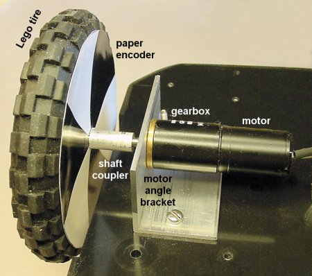
Tire, visual encoder disc, coupler angle bracket, gearbox, and motor.
The All Right robot has two wheels attached to the base. Maxon gearmotors provide the mechanical power. At first, I was concerned that such small motors might not possess the strength or speed to carry such a (relatively) heavy robot. However, they run quite well.
The shaft coupler (pages 21-50 of IRB) and the motor angle bracket (pages 403-406 of IRB) are both made of aluminum. Neither part shows any signs of stress during operation. I’d use this approach for future robot designs.

Teflon block recessed screw slide.
Because this robot has two wheels in the center, it needs something on the back and the front of the base to slide on.
On the corners of the base, I installed four fix-mount Teflon blocks that I sawed off from scrap chunks that I got on eBay. Teflon is very slippery, which decreases the frictional resistance as the robot slides on the blocks.
Alternatively, you can make round rollers (page 400 of IRB) instead of blocks. If your robot tends to slide beyond its mark, rather than stop on a dime, consider the neat trick on page 280.
Putting it all together, let’s see how well the robot performs:
Notice that the robot earns its name, “All Right”, from the method it uses to solve the maze. Whenever the robot can turn right, it does so. That explains why it sometimes takes all the turns that result in a dead-end branch, while other times it skips turns completely. They were either right turns or left turns.
At the actual ChiBots contest, the robot successfully completed the maze and signaled the end with a pirouette. However, the robot’s mass and its strict 90-degree turns caused it to be slower than the top competitor. Mike Davey’s robot was smaller and cut corners at intersections, which earned it first place that day.