

As you saw in the video of the robot driving backwards and forwards on the previous page, this is a fairly simple design.

Back-And-Forth robot schematic.
B1: A direct current (DC) power source with a voltage between 4.5 V and 18 V. This range was chosen from the minimum power supply requirement of the chip (IC1) to the upper limit of the input pins. You should choose a battery within this voltage range that provides the desired speed based on your motor (M1).
SW1: Power switch. When switched off, the battery is electrically disconnected. This means no current flows and the robot does nothing.
M1: A gearmotor (not a plain motor) with sufficient horsepower to push and pull your robot platform at a moderate speed. If the robot moves too quickly, it will smash into obstacles due to momentum, before it has time to change direction based on the switch press.
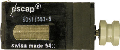
escap M915 L61 flat rectangular gearmotor.
Be sure your motor doesn’t consume more than 400 mA of current, or else IC1 will not be able to provide enough power to get the motor to turn. I chose a nice little compact escap motor, which I obtained, used, from eBay. (Before you write to me -- no, sadly, I don’t know where to obtain some more.)
IC1: IXDI604 (or obsolete IXDI404) dual inverting driver. Make sure the chip name starts with “IXDI” -- NOT “IXDN”, NOT “IXDF” and NOT “IXDD”. It is absolutely essential for the outputs to generate signals that are the opposite (inverting) of the inputs for this circuit to work.
This chip is officially intended for driving MOSFET transistors. As long as your motor doesn’t need more than 400 mA continuously, then the chip will be fine. But, if your motor refuses to turn or the chip gets hot, then your motor or robot is too large for this circuit.
R2 and R3: 22 kilohm resistors. These resistors return signals from the outputs into the opposite inputs (described in detail over the next several pages). The relatively high resistance allows signals coming from the bumper switches (R2 and R3) to override the output values. If you’re familiar with pull-up or pull-down resistors, then you can think of these resistors as performing the same function. The resistors provide default values to the input pins when the switches aren’t pressed.
SW2 and SW3: Normally open (disconnected) switches. I picked snap-action switches because they have a large actuator and require very little force to activate. Any switches will do, so long as the robot has enough strength to push them when contact is made with an obstacle. You can even wire additional switches in parallel, to provide greater obstacle detection coverage.
When the power switch (SW1) is turned on, the battery connects to the power supply pin (Vcc) of the motor driver chip (IC1). As the chip powers up, the output voltages are fed back into the input pins to provide a default starting state. (Technically, the initial state is random. You could add a 220 kilohm resistor from pin 6 to pin 7 to ensure the forward state is always chosen at startup.)
It helps to look at a simplified wiring diagram, where extraneous text and parts do not appear.
1. Forward state. No bumpers pressed.
To make the example concrete, let’s assume the power supply is 6 V. On IC1:
Output A and B also provide power to the motor (M1). The motor spins forward because it receives high (6 V) on one terminal and low (0 V) on the other terminal. The robot will continue to drive forward, because the output pins continue to provide the same values to the input pins.
Neither switch (SW2, SW3) is pressed. So, they have no affect on the circuit. Let’s see what happens when a switch is pressed.