

As shown on previous pages, I etched some beautiful color printed circuit boards. This was the perfect occasion to select some novel components, such as a clear DIP socket.

Chip in clear socket on red printed circuit board.
On Shore Technology part number WMS-080Z is available from Digi-Key (ED2680 $0.26). It is open frame and uses machine pins.

Clear DIP socket.
Unlike standard black plastic sockets, the clear socket uses a slightly flexible material than reminds me of old Jell-O that has been in the refrigerator far too long.
The carrier is described as “wash away”. The clear portion is designed to disappear completely during normal circuit board power washing. I have no idea why this is useful -- I bought it because it is clear.
Dissolving DIP socket animation.
If you have enabled animated GIFs in your browser, you can see the socket dissolve in water (above). I photographed this over the course of an hour. I assume the material disintegrates and detaches much more rapidly when shaken, sprayed, or provided a water supply greater than two tablespoons.
The next day, most of the machine pins were completely separated and loose, although some residual clear material remained because I hadn’t put any effort into fully cleaning it.
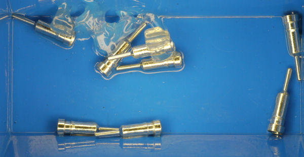
Pins after washing away DIP carrier.
Unfortunately, there is a problem with the clear sockets if left intact. I was already a little worried that they would degrade over time due to humidity. But, it turns out that isn’t the biggest issue.
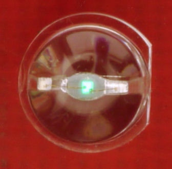
Dimly lit LED due to current leakage.
The Sandwich robot has LEDs on the left and right sides of the boards for decoration and to indicate which sets of sensors see more light. In the assembled circuit, I noticed that the “unlit” set of LEDs had a very slight glow.
I thought maybe I had ultra-efficient LEDs, a bad comparator chip, overly-sensitive transistors, or defective substrate due to the red or blue PCB color. Removing the comparator chip completely did not affect the dimly lit LEDs. The base of the transistor was no longer electrically connected in the circuit, yet it still supplied current to the LEDs.
When I measured the resistance of the clear DIP socket in isolation (not on the board), I measured 40 megohm resistance between pins. Uh oh. A standard DIP socket measures as infinite (some resistance that is too high for the multimeter to measure). That means the clear socket is leaking current between pins.
The LM393 comparator has open collector outputs. It either drains current (0V) or it disconnects. Thus, when the LM393 comparator disconnects its output, the leakage from other pins is amplified by the transistor to provide a tiny current flow that lights the LEDs.
This problem is solved by either:
I guess this is my way of saying that you really shouldn’t buy the clear DIP socket for use on your boards, because it is going to introduce issues unless you wash it away like it was intended.
A circuit board by itself is not a complete solution. Next, we'll check out other pieces of the robot.