

(article continued from previous page)

The test PCB has two large flat test pads to touch the LED against, rather than alligator clips. This makes it easy to quickly see the color of an LED, and it allows testing of surface mount LEDs as well.
If the LED polarity is incorrect, the LED won’t light. No big deal. Just flip the LED around. This makes it easy to verify the positive and negative leads before soldering an LED to a circuit board.
Since the LED tester is connected to a 9 V battery, it can provide almost that much voltage (minus some voltage for the circuitry). But, most LEDs are only guaranteed to resist a reverse voltage of 5 V. Does that mean the LED tester could damage a LED with the leads on the wrong pads?
To test the worst-case effects, I tried hooking up various LEDs backwards to a 30 V source. But, there was no measurable current flow with no visible damage. I can’t quite figure that out. I guess the specified 5 V maximum is conservative. In reality, perhaps most modern LEDs are quite robust to reverse voltages? I wouldn’t rely on that fact in a circuit, but for test purposes, it seems acceptable if an LED encounters a brief 9 V reverse voltage. Furthermore, because the LED tester has a low current limit (less than 30 mA), the likelihood of damage seems remote.
The LED test pads are fully exposed with only a small gap between them. It is likely that an errant screwdriver or a long LED lead will accidentally connect the pads together, shorting them. An accidental short can cause a catastrophic failure in a most circuits. However, since this circuit is current-limited, a screwdriver or any other conductive material will only pass 30 mA in the worst case. Nice feature, huh?
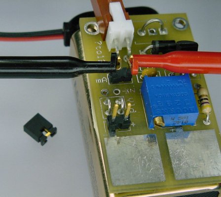
A two pin header with the shorting jumper removed makes it possible to measure the current passing through using a multimeter.
By turning a potentiometer, this LED tester can be adjusted to produce a steady current from 2 mA up to 26 mA -- regardless of the voltage needed by the LED.
For example, when set to 10 mA, a red LED needing 1.7 V will be supplied exactly 10 mA. Then, without making any adjustments, a blue LED needing 3.2 V will be supplied exactly 10 mA. The voltage changes automatically but the current remains constant.
To measure current, the electrons must be routed into multimeter and then back into the circuit. But, during normal operation the electron’s path must be uninterrupted.
A two-pin header on the board is normally connected with a shorting jumper, which allows the current to flow into the test LED. With the jumper removed, the multimeter probes can be attached to the header pins to allow the current to first pass into the multimeter to be measured. By observing the current value on the multimeter display, you can accurately dial the output of the LED tester. After that, the LED tester will supply this current regardless of the LED connected to it.
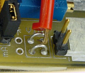
Test point hookups created from simple half loops of wire.
The LED tester includes test points for measuring the voltage of the LED.
I hate it when a multimeter test hooks pop off a circuit, which is why these test point loops are made by connecting two holes (like ground-to-ground) on the PCB with a piece of wire. Wire loops are inexpensive ways of providing a sturdy connection for multimeter test hooks.
Measuring the voltage of the LED at the desired current level is critical for calculating the value of the resistor needed for whatever circuit the LED is going into. For example, let’s say you have a blue LED that you want to light at 15 mA from a 5 V power source. On the LED tester board, the voltage measures 3.2 V @ 0.015 A (which is 15 mA).
5 V - 3.2 V = 1.8 V will be used by the resistor1.8 V / 0.015 A = 120 ohms resistor value
By using a 120 ohm resistor in series with that blue LED and a 5 V power source, the LED will consume 15 mA.