

(continued from previous page)
It gets reasonably cold in Chicago during the winter. Six thermistors were placed in a cooler (or ice chest) outside overnight. The cooler should ensure that they either aren’t affected or are equally affected by indoors temperatures when they are brought inside to be measured.
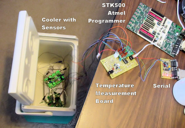
Apparatus for measuring multiple temperatures at the same time, starting with the temperatures in a cooler.
The test setup consists of:
Upon bringing the closed cooler inside (with Molex connectors hanging out), I was impressed to find that the thermistors were all within one resolution of each other: 14.7°, 14.9°, 14.7°, 14.7°, 14.9°, 14.7° Fahrenheit. After warming up for a day outside of the cooler, the sensors were again all within one resolution of 72.4° Fahrenheit. Fantastic!
These results are somewhat due to precision resistors from the same lot, somewhat due to the thermistors being from the same lot, somewhat do to the precision resistors being kept at the same temperature, and somewhat due to the thermistors being read four times over the course of a second and the results averaged.
As part of the first temperature test, I wanted to find a way to even out temperature fluctuations due to the indoor heating system. That is, I wanted to measure a stable room temperature.
A took a large piece (about 6 pounds) of scrap aluminum and screwed a heat-shrink-tubing-covered thermistor to it. I then covered the sensor with a fender washer.
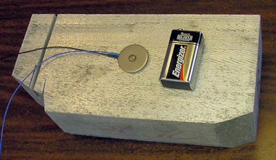
Big chunk of aluminum with temperature sensor.
The idea is that aluminum is thermally conductive (easier to reach room temperature and the heat distributes evenly) but the block has a large thermal mass (slower to change due to random air currents). Think of it as a thermal capacitor.
Unfortunately, when I held my hand against the washer the temperature started rising. It would have been better to encase the thermistor inside of two aluminum blocks.
Here is a really huge graph showing the temperature of all six thermistors from 14 degrees to 72 degrees Fahrenheit over a period of 2400 seconds (40 minutes). The chart is annotated with various points of interest.

Chart of six temperature sensors warming from winter cold to indoor heating.
For the first 10 seconds, the sensors remained in a closed cooler. All six sensors stayed at approximately 14 degrees Fahrenheit. This demonstrates that the sensors match well and that the cooler does a good job of insulating.
Now that we’ve established that the temperature sensors are consistent and follow the expected behaviors, we can proceed to testing the motor driver chips, heat sink, and copper fills on PCBs.