

(continued from previous page)
Robots include several components that can get hot during usage. Primarily, the hottest parts in most hobby robots are the voltage regulator and the motor drivers. On industrial and combat robots, the batteries and motors can also get very hot.
The motor drivers on Roundabout are extremely simple to use but are relatively weak. This is because the chips are meant for driving power MOSFETs, not motors. Nevertheless, this provides an excellent case for testing stressed motor driver chips.
When a chip is working hard, it gets hot. When a CMOS-based semiconductor gets hot, the resistance increases. The higher the resistance, the lower the power output. That’s not good.
In a motor driver, a higher resistance reduces the efficiency and current delivered. That is, the robot’s performance will decline as the motor drivers heat up. If we can determine a technique for keeping the motor drivers cool, we can improve the efficiency (battery life) of the robot and deliver more power to the motors.
An amusing technique for delivering more power is to solder motor driver chips directly on top of each other. The pins of each chip must be soldering to the identical pins of each other chip.

Single motor driver (left) versus two motor drivers soldered together in a stack (right).
This trick requires that the chips’ outputs are based on CMOS or MOSFET technology. (Bipolar and other technologies will suffer from thermal runaway and self destruct.)
Theoretically, the motor driver performance should follow the formula for parallel resistors. If one chip has the equivalent resistance of 5 Ω, then two chips soldered together should have the equivalent resistance of 2.5 Ω. We’re about to test if that is really true or not.
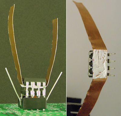
Double-stacked motor driver with copper heatsink and thermal paste in the middle.
Common sense suggests that a limitation of stacking chips directly on top of each other (rather than placing them side-by-side on a board and simply wiring them together) is that the epoxy packages are going to retain heat, which will negatively affect performance. Heatsinks are commonly used on hot chips to radiate heat away. Can we create our own DIY heatsink with a strip of copper and thermal paste in a motor-driver chip sandwich?
The last factor we'll be testing is the amount of copper on the printed circuit boards (PCBs). Recall from the first page of this article that the Roundabout v1.5 circuit board has no copper in the unused locations, whereas the v2.0 boards have all the blank areas filled in with copper squares.
It should be noted that the v2.0 boards also include thicker traces, 0.060 inch rather than 0.040 inch, for the motor drivers, flyback diodes, and motor connectors. (Technically, PCB manufacturers indicate that only 0.025 inch traces are required for up to 1 amp of current, which is higher than we'll be testing.) Because the motor driver power flows directly through these wires, the lower trace resistance and direct heat dissipation may marginally impact the test results.
Will the total added copper on the PCB wick away enough heat to be worth recommending?
It is difficult to create a good repeatable test with a real motor for several reasons.
Since I only care about motor driver temperature and performance over a steady state, I chose to use power resistors instead of a motor for these tests. Unlike common resistors, power resistors are designed to keep their values and dissipate larger amounts of heat.
Many, many values of power resistors are readily available. The simulated motor load (current and power usage) is easily calculated using the power supply’s voltage and the power resistor’s resistance, fed into Ohm’s law
For load testing, I want to be able to add a variety of resistors in parallel to decrease the resistance (increase the current and thus the power usage). Rather than connecting the power resistors together with alligator clips, I spent a little time to make a kit.

Caliper box reused with brass strips for load testing.
The load testing kit consists of a repurposed foam-padded plastic caliper case. The brass square stock (3/8″ thick) has screw holes tapped from end to end. Power wires and resistor wires are connected to the brass rails using brass screws. One rail is for positive and the other rail for negative.

Brass rails and screws hold wires and dual blinking LEDs with reverse polarity diode protection.
In the center of the rails are two blinking LEDs to indicate the box is powered on. Blinking LEDs were chosen because they operate up to 12 volts and are self-regulating (no voltage or current regulators are required even as the applied voltage varies from 5 V to 12 V).
Each LED is connected in series to a Schottky diode to protect against reverse current. As such, the rails can switch from positive to negative (as might occur when simulating a change in motor direction on a robot) without harming the LEDs.

Larger-wattage resistors held in Molex connectors.
Even though the connectors aren’t designed for it, the power resistors slide into Molex female KK connectors. Believe it or not, it’s a pretty good friction fit. You can remove the resistor and swap it for another.
I tried to find some sockets that are designed to fit the power resistor leads, but I had no luck.
Another option would have been to screw the resistor leads to the brass rails. This would likely result in superior heat dissipation, but would take longer per swap and would stress the resistor leads.
After a little more information, the next page presents the thermal results in three charts.